Conference Room Combine Processor
The HAL System Room Combine Processor is designed to simplify the task of configuring the audio system for a set of rooms containing movable walls that can be opened and closed in a variety of ways (configurations that are common in hotels, churches, schools, and conference centers). It is also perfectly suited for meeting rooms that do not combine since it makes paging and background music feeds into such rooms automatic and easy.
For more details on the Conference Room Combine Processor's functionality, see Conference Room Combine.
We advise reading Introduction to Conferencing before diving into the Conference Room Combine block.
Included here is basic information for adding a Conference Room Combine Processor block to your system.
- Click the Processing tab to open the Processing Workspace.
- In the palette area, click the DSP tab.
- Expand the Conferencing category of blocks.
- Click and drag the Room Combine: Conference block into your Processing Map.
- Adjust the number of base rooms needed for your room combine (by deleting or adding rooms).
- Wire each base room's inputs and outputs as appropriate.
- (Optional) Create custom names for miscellaneous items on the block: the block name, input names, output names, and paging zone names.
- Open the Conference Room Combine Processor block's properties by double-clicking the block or hovering and clicking the properties icon that appears in the upper right of the block's title bar. From here you can do the following:
- Configure the physical layout of the rooms, specify which common walls are movable or overflow, and provide end users with control over which walls are open or closed.
- Access the individual Room Processor blocks for each possible room, from which you can configure a wide variety of parameters, create additional control links specific to that room, and customize the room's main preset or add other presets. For more details, see Conference Room Processor Block.
- Add a Conference Room Combine processor to your configuration and add the required number of Base Rooms.
- Open the Conference Room Combine dialog and click on the Layout and Control TAB.
- Drag available rooms onto the workspace and arrange
- Drag and place a moveable wall icon to the appropriate walls
- If you have background music sources, add a Distributed Program Bus block and wire the required input sources. See Distributed Program Bus.
- This audio is available for selection in all Room Processor blocks. See Conference Room Processor Block.
- Is Paging required?
- Add one or more PAGER1 blocks or Paging Station blocks. See PAGER1 Input Block (RAD) and Paging Station.
- Set up Paging Manager scenarios as required. See User Interface Reference.
- Each Room Processor supports the required Paging Zones. See Conferencing Room Processor Paging Zone Block
- Identify any local AV sources such as DVD, Blu-Ray, CD, computer etc.
- Wire these to Local AV Mixer inputs. See Conference Room Processor Local AV Mixer Block.
- Are microphones required for local sound reinforcement?
- Wire these to Local Auto Mixer inputs. Conference Room Processor Local Auto Mixer Block.
- Is a conference connection required?
- VoIP, POTs, Video Codec etc. See Switchboard.
- Wire to From Far End and To Far End nodes. See Conference Room Processor From Far End Mixer Block and Conference Room Processor To Far End Mixer Block.
- What microphones are required for Far-end Auto Mixer inputs?
- Wire Far End Auto Mixer inputs via AEC blocks. See Conference Room Processor Far End Auto Mixer Block.
note: There are eight AEC blocks per EXP7x expansion device. Typically, one AEC block is required for each far-end microphone. See EXP7x Device
note: See an Introduction to Conferencing for details on where to place AEC blocks and how to determine the correct reference
- Wire Far End Auto Mixer inputs via AEC blocks. See Conference Room Processor Far End Auto Mixer Block.
- First, determine which outputs will be used for what purpose: local room, zone within the local room, recording, overflow, AEC reference, etc. See Introduction to Conferencing.
note: While labeled according to their typical function, Record Out, Room Out and Reference Out may be used in variety of ways. Any of these may be used in part or alone for the uses described above.
- Set up the required base room mixes and wire each of the outputs. See Conference Room Processor Block, Conference Room Processor Room Matrix Mixer Block,and Introduction to Conferencing
note: Room Out is a unique mix of Local Auto Mixer, Local AV Mixer, Distributed Program Bus selection and From Far End signals. It also includes the Paging Zone signal
- Open the Room Matrix Mixer for each Base Room and set the required mix
note: Reference Out mix always follows the Room Out mix minus the local microphone mix. This mix also includes the Paging Zone signal.
note: Record Out is a unique mix of Local Auto Mixer, Local AV Mixer, Distributed Program Bus selection and From Far End. It does not include the Paging Zone signal
- Open the Room Matrix Mixer for each Base Room and set the required mix
- Open the Room Matrix Mixer for each Base Room and set the required mix
- Set up the mix for To Far End outputs
- Open the To Far End Mixer for each Room Processor and set the desired mix of Far End Auto Mixer, Distributed Program Bus selection and Local AV Mixer signals. See Conference Room Processor To Far End Mixer Block.
- Do you require a reference for AEC blocks? See Introduction to Conferencing.
- Use Reference Out if you do not want microphones in the reference
- Use Room Out if you want microphones in the reference
- What processing do room outputs require?
- Add EQ, Compression, etc as required and wire room outputs to the appropriate blocks
- Use multichannel and tracking blocks if room and reference need to mirror each other
- You may want remote linking to vary depending on the Room Processor. For an example of changing which remotes are active and which ones need to track, see Control Linking in a Room Combine
- Use custom Conference Room Processor presets to alter linking, input mixer participants, output mixes or processing external to the Room Processor as required. See What aspects of each room can I customize?

| UI Element | Purpose |
|---|---|
| Distributed Program Bus flag |
Represents the automatic inclusion of the Distributed Program Bus channels |
| Far End Auto Mixer inputs |
Connection point for wiring microphone inputs that will be sent to the far-end to a Base Room These are typically preceded by an AEC block. See: EXP7x Device. See: Conference Room Processor Block See: Conference Room Processor Far End Auto Mixer Block Click <Add> to add another Mic In node, or wire a Mic input directly to the <Add> node to automatically create a new node. |
| From Far End input |
Connection point for a far-end input to a Base Room. Typically a paired conference connection with the To Far End output. See: Conference Room Processor Block See:Conference Room Processor From Far End Mixer Block. See: Switchboard. |
| Local Auto Mixer |
Connection point for wiring local microphone input to a Base Room Click <Add> to add another Mic In node, or wire a Mic input directly to the <Add> node to automatically create a new node. Use the <Add Cascade In> flag to cascade in another Auto Mixer (specifically, the AM2 RAD). To add the AM2, drag it from the I/O tab (after adding it in the Hardware Workspace) and drop it on the flag. You can cascade multiple AM2s. Each time you add one, another flag appears, ready to accept the next AM2. |
| Local AV Mixer |
Connection point for wiring local line input to a Base Room Click <Add> to add another Line In node, or wire a Line input directly to the <Add> node to automatically create a new channel. |
| Zone flag |
Represents the room's paging zone (and automatic connection to the paging system) |
| Reference Out |
Connection point for wiring a reference out for use by AEC blocks used with microphones connected to Far End Auto Mixer inputs. Always follows the Room Out mix minus the Local Auto Mixer mix. See: Conference Room Processor Block. |
| To Far End output |
Connection point for wiring an output for the far-end. Typically a paired conferencing connection with the From Far End input. See:Conference Room Processor Block. See: Conference Room Processor To Far End Mixer Block. See: Switchboard. |
| Record Out |
Connection point for wiring the Record Out mix. May be a unique mix of Local Auto Mixer, Local AV Mixer, Distributed Program Bus Selection and From Far End inputs but does not include Paging. Output may be use for overflow, zone output or recording all or part of a room mix |
| Room Out |
Connection point for wiring the Room Out mix. May be unique mix of Local Auto Mixer, Local AV Mixer, Distributed Program Bus Selection and From Far End inputs and includes paging. Reference Out always follows Room Out mix minus the Local Auto Mixer signal. |
| Add Room button |
Add another base room to the block. You can have a total of 7 base rooms in a single Conference Room Combine Processor block. To delete a base room, click the red X in the lower right corner of the room. |


| UI Element | Purpose |
|---|---|
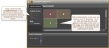
| Layout & Control tab |
Use this tab to arrange the base rooms in the proper physical layout, to specify which walls are movable, and to create control links that give end users a way to indicate which walls are open or closed. When first opened, help text appears in the Layout work area providing guidance on how to get started. See below for a more detailed description of the Layout & Control tab. |
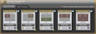
| Room Processors tab |
This tab contains the Room Processor blocks for each possible room—base rooms as well as combined rooms. To customize the audio processing for a room, open its Room Processor properties and configure from there. The Room Mix button takes you directly to the Room Matrix Mixer inside the Room Processor where most control linking related to levels and mix is done. The Selection link provides quick access to the Distributed Program Bus Selector inside the Room Processor. See below for a more detailed description of the Room Processors tab. |
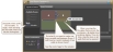
After arranging the base rooms and designating which walls are movable, you need to provide end users with the ability to tell the system which walls are open and which are closed. There are two options available for providing end users with this control:
- Link the Toggle controls (associated with each movable wall) to a DR, allowing the end user to specify if a certain wall is open or closed.
- Link the Selector control (associated with the list of possible room combinations) to a DR, allowing the end user to select which room configuration is currently active. This approach has one limitation. If there are more than 20 possible room combinations, you cannot link the Selector control to a DR, as the DR would be incapable of displaying all of the options. In this case, it would be best to use the Toggle approach.
warning! Once you have linked the Room Combinations Selector control, you cannot make changes to the room and wall layout. If changes are needed, you would have to remove the Selector control link, make your changes, and then re-link the Selector control.
note: Remember that, for testing purposes, you can work with these controls within the software. For example, you can select or deselect a wall's Toggle control to indicate that the wall is open (Toggle is selected) or closed (Toggle is deselected). You can also select an option in the Room Combinations Selector control.
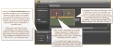
Once you provide the details of a room combine layout and which of its walls are movable, Halogen is then able to calculate the number of possible room combinations. Each standalone room and room combination is seen by the HAL System as a unique room, and each room is given its own Room Processor within which you can configure processing specific to that room.

For more details, see Conference Room Processor Block.
 See Also