Designing the audio for a room combine environment is easy, right? It's no big deal that the system must adapt to changing physical spaces. In fact, it's probably one of your favorite types of systems to design. Or is it?
Our guess is that you're shaking your head no while memories of merged automixer nightmares, complex matrices, myriad presets, and math and control-intensive designs swirl through your mind. But what if we told you that designing a HAL System room combine is SIMPLE? Would you believe us? What if we went on to say that not only is it simple, but, unlike the matrix mixer blobs to which you've grown accustomed, it actually LOOKS like an audio system? Hard to believe? And to further bend your mind, what if we told you that a HAL System room combine design uses a fraction of the DSP resources required by existing solutions? Too good to be true? Not at all. Read on to learn more and to get started with the simple task of designing your room combine system.
The HAL System Room Combine Processor is designed to simplify the task of configuring the audio system for a set of rooms containing movable walls that can be opened and closed in a variety of ways (configurations that are common in hotels, churches, schools, and conference centers). It is also perfectly suited for meeting rooms that do not combine since it makes paging and background music feeds into such rooms automatic and easy. In these situations, audio inputs and outputs as well as remote controls for volume and source selection must change based on the configuration of the rooms. Most existing room combine solutions force designers to think about all the possible rooms all at once while working with all the parameters in a giant matrix mixer. The experience is akin to juggling five flaming swords while simultaneously riding a unicycle and reciting a Shakespeare sonnet!
The HAL System Room Combine Processor simplifies the design of a room combine audio system by allowing you to think about one room at a time, without worrying about specific walls or previous configurations for other room combinations. In other words, you can get off that unicycle and drop those flaming swords! But the HAL System room combine is so simple, you can probably keep reciting the sonnet!
Let's say your room combine consists of three base rooms: 
And let's say that movable walls allow you to create the following rooms: 
As you can see, there are five possible rooms. Using the Room Combine Processor, you lay out the room configuration and designate which walls are movable. You then choose one of the rooms and configure its inputs, outputs, and controls. You then choose another room, and configure its inputs, outputs, and controls. You continue this process until you've configured all five rooms. This simple procedure combined with the streamlining provided by the Distributed Program Bus and the HAL Paging System make it possible for you to complete a room combine design with a minimum amount of wiring and time ... without creating a single preset!
How is this possible? The Room Combine Processor includes the underlying flexibility in DSP behavior required for rerouting and processing audio when the room configuration changes. In addition, the block includes the logic required to understand the different wall configurations and how to reconfigure the audio based on the current configuration. The complexities you've experienced in the past are still there, but they're handled backstage, leaving you applauding in the audience at the flawless performance of this amazing block!
The information below provides the basic concepts and high level work flow you need to understand before working with the Room Combine Processor block. Subsequent sections of this topic dig a bit deeper into specific aspects of working with the block.
To understand how the Room Combine Processor works, you must first understand its key building blocks: base rooms, the base room arrangement, and movable walls.

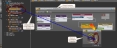
To the left is an image of a Room Combine Processor block
Base Room Configuration
The block now knows how many base rooms there are, but to make sense of them, it also needs to know how the rooms are arranged. You provide this information in the block's properties dialog box (on the Layout & Control tab) by simply dragging the rooms into a drawing area and arranging them appropriately. In our example, the rooms are arranged as shown here: 
Designation of Movable Walls
The final key piece of information needed by the Room Combine Processor block is which walls are movable. Knowing both the arrangement of the rooms and which walls can be opened and closed, the block is able to determine how many actual room configurations are possible. To provide this last key piece of information, you simply drag a movable indicator (in the block's properties dialog box) onto the room arrangement and use it to specify which walls are movable. The result looks like this: 
The dark blue lines indicate that the wall between Rooms A and B is movable and the long wall separating Room C from Rooms A and B is movable. Using this information, the block calculates that there are three possible room combinations ( A|B|C, A+B|C, and A+B+C), producing a total of five rooms that need to be configured (as shown here from the Room Processors tab): 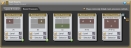
Note also, in the room arrangement graphic, that each movable wall has a checkbox and a control associated with it: 
Selecting a checkbox (manually or via a linked remote control) tells the HAL System that the associated wall is open. The system then activates the room configuration that results from the opening of the wall. On the Room Processors tab, a green lightning bolt indicator tells you which rooms are currently active: 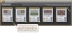
note: As base rooms and walls are arranged in the Room Combine property dialog, a unique Room Processor is created for each base room combination (For example a room processor could be created for room combination A, B, C, A+B, B+C, and A+B+C). The total number of Room Processors in the configuration is calculated by adding together the Room Processors assigned to each Room Combine block in the configuration. To prevent the creation of an excessive amount of Room Processors in the configuration, additional walls and base rooms cannot be added to any Room Combine blocks once the total number of Room Processors in the configuration exceeds 100. Depending on the layout of rooms and walls in a Room Combine block adding an additional wall could result in the addition of anywhere from a couple of new Room Processors to well over 100. In the off chance the addition of a wall to a room combine layout is permitted but takes the total number of room processors above 150 the configuration can no longer be applied to a HAL.
In reality, you would probably wire in your inputs and outputs before arranging your base rooms and specifying which walls are movable—the process described above. But we wanted to be sure you understood those key concepts before moving further into the room combine process. So we'll back up a bit and return to the original Room Combine Processor block—the place where you specify how many base rooms you have. 
As you can see, each base room includes an Auto Mixer and a Mixer. You wire microphone input(s) to the Auto Mixer and can also add one or more cascaded Auto Mixers (namely, the AM2 RAD). You wire all other local inputs to the Mixer. You can add more inputs to both the Auto Mixer and the Mixer by wiring to or clicking its <Add> node. Each base room also includes all the Distributed Program Bus channels (if any have been configured)—as noted by the blue Distributed Program Bus rectangle at the top of the block. In addition, each base room is automatically included as a paging zone in the HAL paging system and automatically shows up in the Paging Manager—as noted by the green Zone rectangle in each room. On the output side, each base room has two outputs: Record Out and Room Out. Just as it says, Record Out is intended for routing output for recording purposes. The Record Out node sends pre-level and pre-page output to its destination—thus avoiding volume changes or page interruptions from being recorded. The Record Out is also useful as an overflow output into zones that have their own paging zone and volume control. The Room Out is the output you want reinforced in the room.
The beautiful thing (or ONE of the beautiful things!) about this Room Combine Processor block is that you don't have to think about any other room combinations when setting up the inputs and outputs to a base room. You can simply focus on that room only.
Now that you've wired your inputs and outputs, created your room arrangement, and designated which walls are movable, you can configure the details of each possible room. We'll continue with the example we used at the beginning of this section (with a few additional inputs added for good measure). The example includes three base rooms arranged in such a way that five different rooms are possible. Your job now is to configure the audio for each of these five rooms. And again, although we've stated this already, we want to emphasize once more that you can focus entirely on the room you're configuring without even considering the needs of the other rooms! What signals should be heard in this room? What audio processing is needed for this space? How should the digital remotes work in this room?
Here again are the five possible rooms resulting from our room arrangement, as displayed in the block's properties dialog box (the Room Processor tab):
Each of the five possible rooms has its own Room Processor block, from which you can configure the appropriate settings for the room. We'll walk through two Room Processor configurations—a base room and a combined room. Let's start with Room A, a base room. Its properties dialog box (opened by double-clicking the Room Processor block or by hovering over it and clicking the properties icon that appears on its title bar) looks like this: 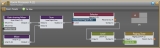
As you can see, the Room Processor contains the blocks (already routed appropriately) that are needed for configuring the room's audio. Configurable blocks included are the Gain-sharing Mixer and Mixer (displaying the inputs wired to the Room Combine Processor block), a Selector (containing the summed output from the two mixers as well as the Distributed Program Bus channels), a Level (for configuring the output volume), and a Paging Zone (for configuring ducker depth and page volume).
Now let's take a look at the room that results from opening the wall between Room A and Room B (or A+B): 
The configuration process is the same, but you'll notice a few differences in the A+B Room Processor's blocks: 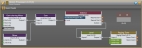
The same blocks are included, of course, but notice the additional inputs in the two mixers. The Room Combine Processor block has combined the inputs from the included base rooms. The Selector block contains Record Out nodes from both base rooms. And the Paging Zone block contains the paging zones and Room Out nodes from both base rooms. In essence, the inputs and outputs from the constituent base rooms now service the combined room and a page into either base room will be heard in the combined space.
The configuration process is the same regardless if you're working with a base room or a combined room. Subsequent sections of this topic cover the configuration steps in more detail, so we'll gloss over those details at this point. The key thing to understand is that each room operates as a separate, unique entity—each having its own configuration. Imagine that all the Room Processors are stored on a shelf (in this example, there would be five Room Processors on the shelf). When you open a wall, the Room Processors required by the room combination that is activated come off the shelf and Room Processors that preceded the wall opening go on the shelf. When you close the wall, or open another wall, the same exchange takes place. Whatever room combination is currently active dictates which Room Processors are active.
So you've linked a DR1 to a Level control in Room A and another DR1 to a Level control in Room B. What happens when those rooms are combined? How do you make sure the two DR1 devices track one another? What about paging? Does someone sending a page to this area need to know that Rooms A and B are now combined? And what about those Distributed Program Bus channels? How do they work in conjunction with the local inputs and what happens to all those inputs when the rooms are combined? Read through this section to learn the answers to all these questions.
tip: The information in this section makes sense only after absorbing the basics of working with the Room Combine Processor block. If you have not reviewed What are the basics of working with this block? (located above), you should do so before continuing.
A key concept that helps answer each of these questions—and a concept that we have mentioned and will continue to mention again and again—is that you think about and configure each room as a separate and unique entity. This concept becomes clearer as you work with the various Room Processors. We'll begin with control linking.
The linkable controls available to you within a Room Combine Room Processor include the following:
- Input and Output Mute controls in the Auto Mixer and
- Input Gain controls in the Mixer
- Output Gain controls in the Auto Mixer and
- Priority control in the Auto Mixer
- Selector control (for selecting input)
- Gain control (for controlling input volume)
- Page Gain control (for controlling page volume)
Let's take a look at how control linking works in a room combine situation—and what better way to illustrate than to use an example. We'll continue to work with the room arrangement introduced in the above section:
Focusing only on control linking, let's set up some remote volume controls for Room A, Room B, and Room A+B. You do so in one of two ways:
- Create a link between the Level control exposed on the room processor block and a remote device (we'll use a DR1), as shown in the following image:

- Or create the link by opening the Room Processor for each room and configuring the link between the Level control and the remote device (we'll use a DR1), as shown in the following image:
After creating this link, you do the same in the Room B Room Processor. You now have a DR1 in Room A that controls the volume in Room A and a DR1 in Room B that controls the volume in Room B.
So what happens when you combine the two rooms? Well, at this point, nothing. We haven't configured the Room Processor for Room A+B. Again, think of Room A+B as just another room—a room that doesn't need to know anything about Room A or Room B. With regard to control linking, we simply need to configure the control links we want for Room A+B. We want the two DR1s to control the volume in the space and to track one another. So we open the Room Processor for Room A+B, open its Level block properties (or link directly to the level control exposed on the room processor), and create a single control link linking the Level control to both DRs, as shown here: 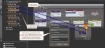
It's really as simple as that! Room A+B now has two DR1s that are linked together. When the wall between Rooms A and B is opened (resulting in Room A+B), this control link (along with the other Room Processor configurations for Room A+B) comes off the shelf and is activated.
In summary, creating control links in a room combine situation is no different from creating them in other situations. You simply work with each room one at a time, creating the control links you need for that specific space. When that room is in use, its control links are activated.
Imagine you're the receptionist at a large conference center and you receive an emergency call for a conference attendee named Jonathan Clark. The caller knows that Mr. Clark is currently in Session 3A. You look it up and see that Session 3A is being held in the Flamingo Room. But your paging system has three possible choices for the Flamingo Room—one as a standalone room, one in combination with the Palm Room, and another in combination with both the Palm and Dolphin Rooms. But you haven't a clue as to which walls they've opened or closed! So you page into the standalone Flamingo Room. Unfortunately, you guess wrong. The Flamingo Room has been combined with the other two rooms and the page is heard only in the Flamingo area. Luckily someone else hears it and notifies Mr. Clark that he has an emergency call. What a pain! There must be a better way!
And, of course, there is—the HAL System Room Combine Processor way! And guess what? It's automatic. You don't have to do anything—except configure your base rooms. Let's take a closer look.
If you've read about or used the HAL paging system, you know that when you drop a Zone Processor or Paging Zone on your Processing Map, that zone automatically shows up in the Paging Manager and is available to page into. The same is true for base rooms in a room combine. When you add a base room to the Room Combine Processor, that base room appears as a zone in the Paging Manager. When you combine two or more base rooms, their paging zones are merged behind-the-scenes such that a page into any of the combined base rooms is heard in the entire space. Returning to our above example, if using the HAL System, the receptionist's page into the Flamingo Room would be heard in the entire area (Flamingo, Palm, and Dolphin).
Let's take a look. Following is the Room Processor properties dialog box for the combined Flamingo, Palm, and Dolphin rooms (A+B+C). Note that the Paging Zone block shows all three paging zones: 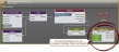
And this is how the three paging zones appear in the Paging Manager: 
Paging into any of these zones will send the page to the appropriate output for the currently-active room configuration.
The Distributed Program Bus behaves in a room combine just as it does in a Zone Processor. Its channels are automatically included in every room's inputs, regardless of the room combination. A Room Processor's Selector block includes the Distributed Program Bus channels along with the room's local input. Linking this selector control to a remote device such as a DR2 or DR3 gives end users the ability to choose between the local input or one of the Distributed Program Bus channels.
note: You cannot mix the Distributed Program Bus channels with the local input channel. To hear a Distributed Program Bus channel, you need to select it. If your situation requires the mixing of these channels, do not use the Distributed Program Bus. Instead, wire the channels as local input to the room's Mixer.
As discussed previously in this topic, each possible room in your room combine has a Room Processor block associated with it. You access these blocks by opening the Room Combine Processor block's properties and then clicking the Room Processors tab. From within a room's Room Processor, you can configure such things as the background music you want, the control links (or other links) that are needed, the volume for the room, the ducker depth and volume of pages, and so on. The Room Processor serves as a mini Processing Map for the room. You cannot drag and drop anything onto the map, but you can set many properties. Anything you customize in the Room Processor pertains to that room and that room only. You do not have to worry about a setting's impact on other room combinations. For more details on what you can configure and how to configure it, see Configuring Individual Room Processors.
But what if you want to include processing that isn't available in the Room Processor? You can accomplish this by using one or more presets. Each Room Processor comes with its own main preset—and the ability to add more presets. These presets pertain only to the room represented by the Room Processor. When the room is not available (in other words, the wall configuration has resulted in other rooms), its presets are deactivated. When the wall configuration changes, making this room available, its configuration comes off the shelf and its preset(s) is(are) activated.
The main preset included in each Room Processor cannot be deleted and is initially empty. When you create a link within the Room Processor, it is added to the preset with an activation state of true. (The link is also added to the Baseline, but with an activation state of false.) You can choose how to work with this main preset, as follows:
- If, when a room is activated, you want the room to return to its most recent state, you should leave the main preset mostly empty (except for control links).
- If, when a room is activated, you want the room to return to a known state, you should save the relevant blocks to the main preset.
You can add other presets to the room as well. For example, suppose a room could be arranged in one of three ways, with a head table on a different wall depending on the current needs. In this case, you could create a different preset for each possible arrangement. Remember, however, that the room's main preset is always active (as long as the room is active). To better understand the use of custom presets, you may want to review
When you designate in the Room Combine Processor Layout & Control tab that a wall is movable, that wall then contains a Toggle control for designating if the wall is open or closed: 
As with all controls, you can test these wall controls before any hardware is installed by manually selecting or deselecting them within the Halogen software. But you eventually need to provide end users with the ability to designate which walls are open or closed. To do so, you simply link these Toggle controls to a DR or to some other remote control hardware. The end user can then designate which walls are open and which ones are closed. With this information, the HAL System then knows which rooms to activate (in other words, which configurations to take off the shelf).
Another option for providing control to end users is to link the Selector control associated with the list of possible Room Combinations to a DR2 or DR3: 
Using the Selector control method, the end user selects which configuration is currently active (instead of selecting which walls are open or closed).
note: If there are more than 20 possible room combinations, you cannot link this Selector control to a DR, as the DR cannot display more than 20 selections. In this case, it would be best to link to the Toggle controls associated with each movable wall.
Following is a typical work flow (in the form of questions) that you would follow when creating a room combine configuration:
- Do you have background music sources? If yes, add a Distributed Program Bus block to your Processing Map as well as the input to the block.
- Are you paging from anywhere? If yes, add one or more PAGER1 blocks or Paging Station blocks.
- How many rooms are in your room combine? Add a Room Combine Processor and then add more rooms to it, if necessary.
- What are the inputs to each room? Add the inputs and wire them to the appropriate room.
- What processing do room outputs require? Add EQ, Compression, and so on. Wire the room outputs to the appropriate output block.
- What is the layout of the rooms in your room combine? Open the Room Combine Processor block and configure the layout of the rooms as well as which walls are movable.
- Do you need to customize the audio processing in one or more rooms? Open the relevant Room Processors to do so.
- Do you want to change any blocks outside of the Room Combine Processor when rooms are activated? Set up the PEQ blocks, output blocks, and any other blocks you want to associate with the room. Add these blocks to the room's main preset.
In reality, you could stop here and have a functioning room combine system. But it's likely you will want to configure remote control of the room configuration and you may also want to customize the processing for each possible room. Open the Room Combine Processor properties dialog to perform these functions.