Conference Room Processor Block
A Room Processor block exists for every possible room in a conference room combine situation. “Room” is defined as a base room or the combination of two or more base rooms. Within each Room Processor is a set of pre-wired processing blocks which you can configure to your liking.
Input mixers include: Far End Auto Mixer, Local Auto Mixer, Local AV Mixer, Distributed Program Bus Selector and From Far End Mixer.
Two output mixers follow the input mixers:
- The To Far End Mixer mixes Far End Auto Mixer, Local AV Mixer and Distributed Program Bus Selector signals for the To Far End output.
- The Room Matrix Mixer is a four-in, three-out matrix mixer that determines the mix for Record Out, Room Out and Reference Out outputs. Available mix sources are Local Auto Mixer, Local AV Mixer, Distributed Program Bus Selector and From Far End Mixer.
See: Room Combine:Conference Processor Blocks
A Room Processor also includes a Paging Zone able to page into the Room Out and the Reference Out mixes.
The input mixers consolidate base room inputs as rooms combine. Room Out and To Far End mixes may be different for each Room Processor. The following figure shows a typical Room Processor and its child blocks:
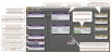
Within these blocks, you can configure audio processing specific to each room as well as create control links for end user control. From the Room Processor, you can also add blocks to the room's main preset, which automatically activates when a room is in use. You can also add custom presets that can include blocks both internal and external to the Room Processor.
Perhaps the most important concept to remember is that each room has its own Room Processor, and the configuration of one room's Room Processor has no impact on another room's Room Processor—even if they contain one or more of the same base rooms. Think of each room in your room combine as a unique entity, and approach each Room Processor as if it is a standalone configuration.
| UI Element | Purpose |
|---|---|
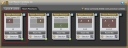
| Room Layout |
Shows the room to which this Room Processor belongs. |
| Preset Icon (upper right) |
To add the entire Room Processor and its child blocks to a preset, click and drag this icon and drop it into the preset (in the All Presets dialog box or in the individual preset properties dialog box). |
| Room Mix Button & Selection link | When the Show commonly linked room processor controls option is checked in the Room Processor TAB, the Room Mix button and Selection Link appear. The Room Mix button opens the Room Matrix Mixer where level control liking is typically done. The Selection link allows linking the Distributed Program Bus Selector without having to open the Room Processor properties dialog.. |
| In Use Round Green Icon (lower right corner) | Its presence indicates the room is in use. In other words, the current wall configuration is such that this specific room exists and its settings are active and heard. |
Base Room:  Combined Room:
| UI Element | Purpose |
|---|---|
| Room Presets Icon |
Launches the All Room Presets dialog box containing preset(s) specific to this room. The room contains a main preset (a Toggle preset) that is created automatically when the room is created. This preset, which cannot be deleted, is activated when this room is in use. If desired, you can customize this preset by adding additional blocks and/or control links to it. Anything you add to this preset is automatically activated when this room is in use. You can also create additional custom presets for each room that can be activated/deactivated by end users. One example would be when the room must be set up to face north today, but east tomorrow. |
| Far End Auto Mixer block |
Automates the mix of multiple microphone input signals into a single output channel. These microphones are used for the far-end conference connection and are typically connected via an AEC block. This signal is only available for far-end mixing. note: In the Room Processor for a combined room, the Far Mic In inputs from all the constituent base rooms are combined when base rooms combine. (See image above of combined Far Mic In inputs) |
| Local Auto Mixer block |
Automates the mix of multiple microphone input signals into a single output channel. These microphones are used for near-end speech reinforcement. Local Mic In inputs may share microphones with Far Mic In inputs. In this case the Local Mic In signal is taken before the AEC block used with the Far Mic In inputs. This signal is only available for near-end mixing. note: In the In the Room Processor for a combined room, the Local Mic In inputs from all the constituent base rooms are combined when base rooms combine. (See image above of combined Local Mic In inputs) |
| Local AV Mixer block |
Mixes multiple input signals into a single output channel. These inputs support typical AV sources like DVD, Blu-Ray, laptop etc. This signal is available for far-end and near-end mixing note: In the Room Processor for a combined room, the AV Line In inputs from all the constituent base rooms are combined when base rooms combine. (See image above of combined AV Line In inputs) |
| From Far End Mixer block |
Mixes base room From Far End inputs when rooms combine. This mix is only available for near-end mixing. (See image above of combined From Far End inputs) |
| Selector block | Allows you to select one of the available Distributed Program Bus channels. This selection is available for far-end and near-end mixing. |
| To Far End Mixer block | Allows you to set the desired mix of Far End Auto Mixer, Local AV Mixer and Distributed Program Bus Select signals for the To Far End output. |
| Room Matrix Mixer block |
Allows you to set the desired mix of Local Auto Mixer, Local AV Mixer, Distributed Program Bus Selector and From Far End Mixer signals for the Record Out and Room Out. The Reference Out mix always follows the Room Out mix minus the Local Auto Mixer signal. This block is where output level and mix level linking are typically done. |
| Paging Zone block |
Creates an output from the HAL Paging System. This block provides the audio processing and control required to duck program audio and insert page audio into the Room Out and Reference Out. note: In the Room Processor for a combined room, the Paging Zones from all the constituent base rooms are combined, meaning a page to any of the zones is automatically sent to all the zones in the combined room. (See image above of combined paging Zones) |
| Splitter blocks |
These blocks have no user parameters. They simply route outputs back to each participating base room. (See image above of combined base rooms) |
| Room Layout graphic | Shows the room to which the Room Processor belongs. |
 See Also