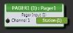
PAGER1 Input Block (RAD)
A PAGER1 Input block represents the audio signal received from this PAGER1 device connected to the corresponding RAD port on the HAL or EXP device. The block provides the audio processing required to prepare the PAGER1 microphone input channel for the HAL Paging System.
- Click the Processing tab to open the Processing Workspace.
- In the palette area, click the I/O tab.
- In the Remote Audio Device Ports category, find the PAGER1 device you want. Click and drag its Pager Input block into your Processing Map.
- (Optional) Customize the block name, channel name, and/or station name (in the green box) by clicking the current name and then typing the custom name in the text box that appears. Click the X to save the name.
note: A RAD does not appear in the I/O palette until it has been added to the system in the Hardware Workspace.
note: You do not have to wire the PAGER1 audio to any other blocks. It is automatically included in the HAL paging system and appears in the Stations column in the Paging Manager. To clearly identify this station, you may want to customize its name (see next step).
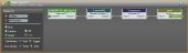
- Open the Pager Input block's properties by double-clicking the block or hovering and clicking the properties icon that appears in the upper right of the block's title bar. The properties include the following:
- a Mic Input block for controlling the sensitivity and level settings for the PAGER1 microphone.
- a Parametric EQ block (2-band PEQ) that allows you to reject noise and compensate for microphone frequency response.
- a simplified Compressor block (with speech-optimized attack, release, and knee settings) that provides the dynamics processing required to handle different paging station users talking louder or softer, or closer to / further from the microphone.
- an output Level block, allowing you to set the nominal volume of the page audio.
- a display of the Paging Station controls (located on the left) that provide the control interface to the paging system.
- Open the Mic Input block's properties by double-clicking the block or hovering and clicking the properties icon that appears in the upper right of the block's title bar.
- In the Sensitivity area, enable or disable the 13 dB Pad and adjust the Gain to the appropriate level depending on the sensitivity of the microphone you plan to use.
- If the PAGER1 microphone needs phantom power, select the +24 V Phantom checkbox.
- Set the volume of the block's output by adjusting the Gain slider or entering a value in the edit box.
- Provide page audio volume control to end users by linking one or more DR1 or DR3 level controls to the block's Level Gain control. You can limit the range of end user volume control by adjusting the minimum and maximum values at either end of the level control. For example, to give the end user 24 dB of attenuation, set the minimum to -24 dB and the maximum to 0 dB. To change these values, click the minimum or maximum value displayed below the slider. An edit box displays in which you can set the Minimum and Maximum parameter values.
- Cause the page audio to mute completely when dialed to the low end of its range by selecting the Off @ Min checkbox. Using the example range described above, checking Off @ Min provides continuous volume control from 0 dB to -23.9 dB and then mutes the audio completely.
- Mute the page audio—without changing the specified Gain value—by selecting the block's Mute checkbox. You can provide end users with control over this Mute parameter by linking the block's Mute control to a Logic In, DR2, or DR3 Toggle control.
- View meter data for the audio signal after passing through the Sensitivity settings as well as after passing through the Level settings.
- Open the Compressor block's properties by double-clicking the block or hovering and clicking the properties icon that appears in the upper right of the block's title bar.
- Set the compressor Threshold so that a nominal input signal sits half way between the Threshold and full scale.
- Set the compression Ratio to allow as much variation in output level as your application can tolerate.
- Use the Compressor block’s output Gain control to increase the output level until the nominal input level (usually -20 dBFS) produces a nominal output level (also usually -20 dBFS).
- If you choose not to use the Compressor, bypass the block using the Bypass checkbox in the lower right corner of the property dialog.
- Open the 2-band PEQ block's properties by double-clicking the block or hovering and clicking the properties icon that appears in the upper right of the block's title bar.
- Use the Low-cut filter to attenuate low frequency noise below vocal frequencies (HVAC rumble, passing trains, etc).
- Use the High-cut filter to attenuate high frequency noise above the vocal range (hiss from sibilance, white noise from nearby fountains, etc). The two parametric filter bands can compensate for microphone variance and further help ‘color’ the page input (add a little bass to a voice, etc).
- If you choose not to use the PEQ Block, bypass the block using the Bypass checkbox in the lower right corner of the property dialog.
- Open the Level block's properties by double-clicking the block or hovering and clicking the properties icon that appears in the upper right of the block's title bar.
- Limit the range of the level control. To do so, open the Min and Max controls edit box by clicking the minimum or maximum value located beneath the slider. In the edit box that appears. set the Min and Max to the values you want.
- Give end users control over the page level by linking the Gain control with a DR1 or DR3 Level.
- Work with the PAGER1 controls on the left of the properties dialog box. Included there is a list of the Paging Scenarios into which the PAGER1 can page. The PAGER1 block can page into only those Paging Scenarios
 that have been added (within the Paging Manager) to this PAGER1. When Scenarios are added to the PAGER1, they appear in this list with adjacent radio buttons. Selecting a Scenario prepares the PAGER1 to page into that Scenario. The Busy, Caution, and Ready indicators display the state of the Scenario:
- If no Zones in the selected Scenario are being paged into through another Scenario, the Ready light illuminates.
- If one or more Zones in the selected Scenario are currently receiving a page through a Scenario of equal or higher priority, the Busy light illuminates.
- If one or more Zones in the selected Scenario are receiving a page through a Scenario of lower priority, the Caution indicator illuminates.
Checking the Talk checkbox initiates a page into the selected Scenario. While paging into an available Scenario, the indicator above the Talk checkbox shows a status of Paging. If the page is attempted into a Busy Scenario (or a Scenario of higher priority overrides the page from this station), then the indicator above the Talk checkbox displays a status of Overridden.
note: When connected to the HAL, the Talk checkbox in Halogen is disabled (because the Talk button on the actual PAGER1 is read only. To initiate a page, you must press the Talk button on the PAGER1 hardware.
- Following the paging indicators is an option for specifying the behavior of the talk button. Push mode initiates a page with a push of the talk button and terminates the page as soon as it is released. Toggle mode however, leaves the Pager1 in page mode until the talk button is pushed again.
- The Font family option specifies the font used for all labels and text shown on the Pager1 device.
For more details about working with the PAGER1 and the HAL paging system, see Adding and Configuring a PAGER1 RAD and About Paging.
| UI Element | Purpose |
|---|---|
| Analog Input (Channel 1) | Name identifying the incoming microphone channel. You can edit this name by clicking it and then typing the new name in the edit box that appears. |
| Station flag | Represents the connection into the HAL paging system. Also includes the Station name that appears in the Paging Manager. To rename the Station, click the existing name and then type the new name in the edit box that appears. |
| UI Element | Purpose |
|---|---|
| Station controls (on left) | Displays the Paging Scenarios into which this PAGER1 can page (configured in the Paging Manager). To select a Scenario, click its radio button. Displays the status of the selected Scenario (Busy, Caution, or Ready). Displays the status of the Paging Station (Off, Paging, or Overridden). To page (or simulate a page) into the selected Scenario, select the Talk checkbox. (When connected to a HAL, however, you must press the Talk button on the PAGER1 hardware to initiate a page.) |
| Talk Mode |
Configure the behavior of the Talk button by choosing between the push and toggle mode. Push Mode configures the talk button to initiate a page as soon as the talk button is pressed, but the page will be terminated as soon as the talk button is released. Toggle Mode configures the talk button to initiate a page as soon as the talk button is pressed, and the Pager1 will remain in the paging state even after the talk button is released. When finished paging push the talk button again to terminate the page. |
| Font Family | Select the font for all labels and values shown on the DR device. You can choose between Times New Roman and Arial fonts. |
| Mic Input block | Provides control over the Sensitivity and Level settings for the PAGER1 microphone. For details, see the previous section (How to Use). |
| 2-band PEQ block |
Allows you to reject noise and compensate for microphone frequency response. Open its properties dialog box to configure its settings. For details, see the previous section (How to Use). |
| Compressor block | Provides the dynamics processing required to handle different paging station users talking louder or softer, or closer to / further from the microphone. Open its properties dialog box to configure its settings. For details, see the previous section (How to Use). |
| Level block | Allows you to set the nominal volume of the page audio. Open its properties dialog box to configure its settings. For details, see the previous section (How to Use). |
 See Also