Switchboard
The Conference Switchboard allows users to easily establish bidirectional connections between a set of up to 32 rooms. For each Endpoint (near-end room) the user is presented with a list of possible Participants (far-end rooms). From the perspective of each Endpoint, the desired connections are made by simply checking appropriate Participant entries in a list. This routing could be accomplished with a matrix mixer, but doing so requires ensuring paired “To” and “From” routing to each room. This is difficult to do without using presets and is not very intuitive to an end user and system controls left behind for end users needs to be intuitive. The Conference Switchboard solves this problem in an elegant way. Each Room has a “To Switchboard” and “From Switchboard” connection with the Conference Switchboard block.
A typical application involves dynamically controlling the conferencing configuration of co-located rooms on a campus. Conferencing in this way is simpler, lower cost and provides better sound quality and lower latency than teleconferencing.
Endpoint (near-end) and Participant (far-end) may be a physical room, VoIP or POTs connection
- Click the Processing tab to open the Processing Workspace.
- In the palette area, click the DSP tab.
- Expand the Conferencing category of blocks.
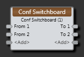
- Click and drag the Switchboard block into your Processing Map.
- (Optional) Customize the names of the block and the input/output nodes by clicking their current name and then typing the custom name in the text box that appears. Click the X to save the name.
note: It is very important that paired To and From connections are properly place on the Block I/O. For example, From 1 and To 1 must correspond to the same room or VoIP connection.
| UI Element | Purpose |
|---|---|
| Inputnode | Connection point for wiring inputs to the Switchboard block. Each input may be sent to any output except its paired output. It is important to properly pair Inputs (from) and outputs (to). For example, From 1 and To 1 are an Input and Output pair that represents a near-end and far-end pair. |
| Output node | Connection point for wiring outputs from the Switchboard block. |
| <Add> nodes | Click to add another Input/Output pair of nodes, or wire to the <Add> node to automatically create a new channel. |
| UI Element | Purpose |
|---|---|
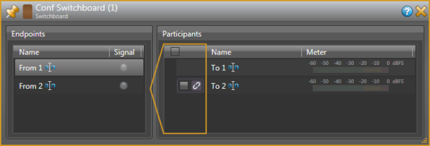
| Endpoints |
To use, click on a “From” endpoint. This represents the room you are setting up a conference from. A list of available Participants (far-end rooms) is presented which excludes the paired “To” output as you do not want to send a To far-end signal back to the originating room. An input Signal Present indicator is provided for each endpoint. |
| Participants |
After selecting an Endpoint, check the Participants that you want to include in the conference to establish the required bidirectional connections. The participant check boxes may be linked to a remote in the selected endpoint room. Meters are provided for each “To” output so you can monitor what is being output to the various participants. |
 See Also