Designing the audio for a room combine environment is challenging. The system must adapt to changing physical spaces, combining audio sources and remote control devices from a number of rooms and be relatively easy for an end-user to manage. This becomes even more challenging when you add conferencing to a room combine environment.
What would it take to include conferencing in a room combine application? It’s not that hard to conceptualize, but often difficult to implement using typical tools. All you need to do is properly combine microphones, AV and from-far-end inputs, acquire an appropriate reference and output signals to appropriate rooms and far-end destinations. Halogen provides a highly integrated Conference Room Combine block that greatly simplifies this process.
Before diving into the Conference Room Combine Block, we strongly advise first reading an Introduction to Conferencing. It provides insight into conferencing in general, other Halogen blocks available to assist in conference system design and an introduction to designing with the Halogen Conference Room Combine block.
OK, now that you’re familiar with the information in an Introduction to Halogen Conferencing, let’s dive into the Conference Room Combine Block.
The Halogen Conference Room Combine Processor is designed to simplify the task of configuring an audio system for a set of rooms that must support conferencing and contains a number of moveable walls that can be opened and closed in a variety of ways (configurations that are common in hotels, churches, schools, and conference centers). It is also perfectly suited for meeting rooms that do not combine since it makes paging, background music feeds, acquisition of an appropriate AEC reference and mixing various local room sources automatic and easy.
In situations where rooms combine, audio inputs and outputs as well as remote controls for volume and source selection must change based on room configuration. Most existing room combine solutions force designers to think about all the possible rooms all at once while working with all the parameters in a giant matrix mixer.
The Halogen Conference Room Combine processor simplifies design by allowing you to think about one room at a time, without worrying about specific walls or previous configurations for other room combinations.
The Conference Room Combine block allows you to setup a number of base rooms. Each base room has a conference I/O section and a local I/O section. The conference portion of a base room has a Far End Auto Mixer to receive microphones that need to be heard at the far-end, a From Far End input to receive audio from a far-end, a To Far End Out to send audio back to a far-end and an AEC Reference Out. The local room portion of a base room has a Local Auto Mixer to mix microphones for near-end speech reinforcement, a Local AV Mixer for mixing local AV or other line-level sources, a Paging Zone for connection to the Halogen Paging Manager, a Record Out and a Room Out. A basic base room for the Conference Room Combine block is shown below:

Let's say your room combine consists of three of these base rooms with moveable walls as shown below:

This configuration creates five possible rooms as shown below:
It is a good idea to work from a diagram showing the layout of the rooms, where moveable walls are located, the location of required audio I/O for each base room and the location of required system controls (remotes) for each base room. The figure below is an example of such a diagram:
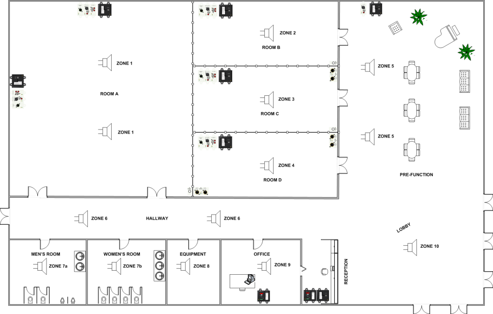
Having a picture of the physical space and its requirements greatly simplifies the Halogen design process. Working from your diagram, typical workflow is as follows:
- Configure the base rooms and add moveable walls.
- Add a Conference Room Combine block to your configuration and add the required number of base rooms. (See Adding the Block to Your System)
- Open the Conference Room Combine dialog and click on the Layout and Control tab. (See Room Combine Processor Block Properties)
- Drag available rooms onto the workspace and arrange.
- Drag and place moveable walls between walls.
- Configure Distributed Program Bus and Paging
- If you have background music sources, add a Distributed Program Bus block and wire the required input sources. (See Distributed Program Bus)
note: This audio is available for selection in all Room Processors.
- Are you Paging into base rooms?
Add one or more PAGER1 blocks or Paging Station blocks. (See PAGER1 Input Block (RAD) and Paging Station)
Set up the Paging Manager scenarios as required. (See User Interface Reference)
note: Each Room Processor supports the required Paging Zone (See Conferencing Room Processor Paging Zone Block)
- If you have background music sources, add a Distributed Program Bus block and wire the required input sources. (See Distributed Program Bus)
- Wire base room inputs:
- Identify any local AV sources such as DVD, Blu-Ray, CD, computer etc.
- Wire these to Local AV Mixer inputs. (See Conference Room Processor Local AV Mixer Block)
- Are microphones required for near-end sound reinforcement?
- Wire to Local Auto Mixer Inputs. (See Conference Room Processor Local Auto Mixer Block)
- Is a conference connection required?
- For VoIP, POTs, Video Codec etc. use a Conference Switchboard. (See Switchboard)
- Wire to From Far End and To Far End nodes. (See Conference Room Processor From Far End Mixer Block and Conference Room Processor To Far End Mixer Block)
- What microphones are required for Far End Auto Mixer inputs?
- Wire to Far End Auto Mixer inputs via AEC blocks. (See Conference Room Processor Far End Auto Mixer Block)
note: There are eight AEC blocks per EXP7x expansion device. Typically, one AEC block is required for each far-end microphone. (See AEC (Acoustic Echo Cancellation) and EXP7x Device)
note: See an Introduction to Conferencing for details on where to place AEC blocks and how to determine the correct reference.
- Identify any local AV sources such as DVD, Blu-Ray, CD, computer etc.
- Wire and set the audio mix for base room outputs:
- First, determine which outputs will be used for what purpose: local room, zone within the local room, recording, overflow, AEC reference, etc. (See Introduction to Conferencing)
note: While labeled according to their typical function, Record Out, Room Out and Reference Out may be used in a variety of ways. Any of these may be used in part or alone for the uses described above.
- Set up the Conf Room Processor output mixes for each room. (See Conference Room Combine ProcessorIntroduction to Conferencing
- Open the Room Matrix Mixer for each Base Room and set the required mixes.
- Room Out is a unique mix of Local Auto Mixer, Local AV Mixer, Distributed Program Bus Selection and From Far End signals. It also includes the Paging Zone signal.
- Reference Out mix always follows the Room Out mix minus the local microphone mix. This mix also includes the Paging Zone signal. This mix may be used for near-end room mix-minus and/or AEC reference.
- Record Out is a unique mix of Local Auto Mixer, Local AV Mixer, Distributed Program Bus Selection and From Far End. It does not include the Paging Zone signal.
- The To Far End Mixer determines the mix for the To Far End output. (See Conference Room Processor To Far End Mixer Block and Conference Room Processor Block)
- Open the To Far End Mixer for each Room Processor and set the desired mix of Far End Auto Mixer, Local AV Mixer and Distributed Program Bus Selection.
- Open the Room Matrix Mixer for each Base Room and set the required mixes.
- What processing do room outputs require?
- Add EQ, Compression, etc as required and wire room outputs to the appropriate blocks.
- Use multichannel and tracking blocks if room and reference need to mirror each other. (See Introduction to Conferencing)
- First, determine which outputs will be used for what purpose: local room, zone within the local room, recording, overflow, AEC reference, etc. (See Introduction to Conferencing)
- Configure each Room Processor:
- You may want remote linking to vary depending on the Room Processor. For example changing which remotes are active and which ones need to track. (See How do control links, paging, and the Distributed Program Bus behave in a conference room combine situation? below)
- Use custom Room Processor presets to alter linking, input mixer participants, output mixes or processing external to the Room Processor as required. (See What aspects of each room can I customize? below)
The information below provides the basic concepts and high-level work flow you need to understand before working with the Conference Room Combine processor block. Subsequent sections of this topic dig a bit deeper into specific aspects of working with the block.
It’s easier to understand how the Conference Room Combine processor works after becoming familiar with its key building blocks: base rooms, the base room arrangement, and movable walls.
Base Rooms

Above is an image of a Conference Room Combine processor. The block displays the base rooms in your room combine and provides connection points for wiring inputs and outputs. A base room is a room that cannot be subdivided. It can be combined with other base rooms to form new rooms, but it cannot be broken down any further. While this example contains two base rooms (Room A and Room B), you can add up to seven total base rooms by clicking the Add Room button at the bottom of the block.
Base Room Configuration
The block now knows how many base rooms there are, but to make sense of them, it also needs to know how the rooms are arranged. You provide this information in the block's properties dialog box (on the Layout & Control tab) by simply dragging the rooms into a drawing area and arranging them appropriately. For our example, we’ll arrange three rooms as shown here:

Designation of Movable Walls
The final key piece of information needed by the Conference Room Combine block is which walls are movable. By knowing both the arrangement of the rooms and which walls can be opened and closed, the block is able to determine how many actual room configurations are possible. To provide this key piece of information, you simply drag a movable wall indicator onto the room arrangement and use it to specify which walls are movable.
The result looks like this:
The dark blue lines indicate that the wall between Rooms A and B is movable and the long wall separating Room C from Rooms A and B is movable. Using this information, the block calculates that there are three possible room combinations ( A|B|C, A+B|C, and A+B+C), producing a total of five rooms that need to be configured (as shown here from the Room Processors tab):
Note also, in the room arrangement graphic, that each movable wall has a checkbox and a control associated with it as shown below:

Toggling a checkbox (manually or via a linked remote control) tells the HAL System that the associated wall is open. The system then activates the room configuration that results from the opening of the wall. On the Room Processors tab, a green lightning bolt indicator tells you which rooms are currently active as shown below:
note: As base rooms and walls are arranged in the Conference Room Combine property dialog, a unique Room Processor is created for each base room combination (For example a room processor could be created for room combination A, B, C, A+B, B+C, and A+B+C). The total number of Room Processors in a configuration is calculated by adding together the Room Processors assigned to each Conference Room Combine block in the configuration. To prevent the creation of an excessive amount of Room Processors in a configuration, additional walls and base rooms cannot be added to any Conference Room Combine blocks once the total number of Room Processors in the configuration exceeds 100. This includes Room Processors created using the standard Halogen Room Combine processor block. Depending on the layout of rooms and walls in a Conference Room Combine block adding an additional wall could result in the addition of anywhere from a couple of new Room Processors to well over 100. In the off chance the addition of a wall to a room combine layout is permitted but takes the total number of room processors above 150 the configuration can no longer be applied to a HAL.
In reality, you would probably wire in your inputs and outputs before arranging your base rooms and specifying which walls are movable—the process described above. But we wanted to be sure you understood those key concepts before moving further into the Conference Room Combine process. So we'll back up a bit and return to the original Conference Room Combine Processor block—the place where you specify how many base rooms you have. Here is its picture again, with its key components clearly marked. Hover over the image to enlarge it, and spend a few moments becoming familiar with each base room's components:

The Distributed Program Bus provides each base room with access to available Distributed Program Bus channels. From within each Room Processor you may select the desired channel and mix as much or little of it as you wish into the To Far End, Record Out and Room Out mixes.
Each room has a set of Far End Auto Mixer inputs to support conferencing. This is where you connect microphones that need to be heard at the far-end. Each of these is typically preceded by an AEC Block. The same microphones may also be wired to the Local Auto Mixer to support local speech reinforcement or Voice Lift. In this case the signal wired to the Local Auto Mixer is taken before the AEC block. It is also possible for microphones wired to the Far End Auto Mixer to be independent of or a subset of microphones wired to the Local Auto Mixer.
A From Far End input is available in each base room. This provides a room input from a VoIP, POTs or other far-end sources used for conferencing.
The Reference Out consists of all signals that will be output to a room minus the Local Auto Mixer signal. Within a Room Processor, Halogen ensures that the Reference Out tracks the Room Out signal when a room mix or level is adjusted, a page occurs and when rooms combine. If an application requires the Local Auto Mixer signal in the reference, the Room Out can be used to drive the room and the reference. The reference output is used by AEC blocks that precede the Far End Auto Mixer inputs. See Introduction to Conferencing for more details.
To Far End is the signal sent to a far-end conference participant. It consists of a flexible mix of Far End Auto Mixer, Local AV Mixer and selected Distributed Program Bus signals.
A Local Auto Mixer provides inputs for room microphones and a docking station for RAD AM2 Auto Mixers. This microphone mix is available for near-end speech reinforcement and may be included in the Room Out and/or Record Out signals. This mix is not available for the To Far End output.
A Local AV Mixer provides inputs for room line-level AV sources. This mix is available for the To Far End Output, Record Out, Room Out and Reference Out.
The paging Zone input provides access to the Paging Manager. When a base room is paged, any room combined with it is also paged. A page and the accompanying ducking of the regular program material are properly dealt with in the reference signal. A page is not available for the To Far End Output or Record Out.
This section is all about inputs and outputs, but it’s worth taking a quick look at a Room Processor and the Room Matrix Mixer at its core to get a better idea of how these signals are mixed and routed. The figure below shows a room A+B Room Processor. Note that this architecture is significantly different than that of the standard Halogen Room Combine block. When base rooms combine, like inputs from participating rooms combine and all outputs are routed to participating rooms as before. However, in addition to the new conferencing elements, the Room Matrix Mixer allows a unique mix of the four available room sources for the Room Out and for the Record Out. This flexibility in mixing opens up new applications for these outputs. For further details see Conference Room Combine Processor.


A beautiful thing about this Conference Room Combine processor block is that you don't have to think about any other room combinations when setting up the inputs and outputs to a base room. You can simply focus on that room.
Now that you've wired your inputs and outputs, created your room arrangement, and designated which walls are movable, you can configure the details of each possible room. We'll continue with the example we used at the beginning of this section (with a few additional inputs added for good measure). The example includes three base rooms arranged in such a way that five different rooms are possible. Your job is to configure the audio for each of these five rooms. And again, although we've stated this already, we want to emphasize once more that you can focus entirely on the room you're configuring without even considering the needs of the other rooms! What signals should be heard in this room? What audio processing is needed for this space? How should the digital remotes work in this room?
Here again are the five possible rooms resulting from our room arrangement, as displayed in the block's properties dialog box (the Room Processor tab):
Each of the five possible rooms has its own Room Processor block, from which you can configure the appropriate settings for the room. We'll walk through two Room Processor configurations—a base room and a combined room. Let's start with Room A, a base room.
Its properties dialog box, opened by double-clicking the Room Processor block or by hovering over it and clicking the properties icon that appears on its title bar, looks like this:

As you can see, the Room Processor contains the blocks (already routed appropriately) needed for configuring the room's audio. Configurable blocks on the left-hand side display the inputs wired to the Conference Room Combine block and determine the mixes available for a room. These input mixes allow the inclusion, exclusion or custom mix of wired sources.
The To Far End Mixer allows you to setup a custom mix of Far End Auto Mixer, Local AV Mixer and Distributed Program Bus Selector signals for the far-end.
The Room Matrix Mixer allows a custom mix of Local Auto Mixer, Local AV Mixer, Distributed Program Bus Selector and From Far End Mixer signals for Record Out, Reference Out and Room Out. Level controls left behind for users are typically linked to level controls in the Room Matrix Mixer. This is especially important if conferencing is involved as it ensures that Reference Out and Room Out signals track each other.
The Paging Zone provides access to the Paging Manager and includes inputs and outputs for reference and room signals. A tracking Paging Zone is required to ensure that Reference Out and Room Out signals track each other.
The Splitter blocks on the right-hand side distribute available output signals to all base room associated with a Room Processor.
Now let's take a look at the room that results from opening the wall between Room A and Room B (or A+B):
The configuration process is the same, but you'll notice a few differences in the A+B Room Processor blocks:

The same blocks are included, of course, but there are some differences:
- Notice the additional inputs on the four input mixers. The conference Room Combine processor block has combined the inputs from the included base rooms.
- The Splitter blocks on the right-hand side distribute Room Processor outputs to all participating base rooms.
- The Paging Zone includes paging for both base rooms. In essence, the inputs and outputs from the constituent base rooms now service the combined room. Paging into either base room is heard in the combined space.
The configuration process is the same whether you're working with a base room or a combined room. Subsequent sections of this topic cover the configuration steps in more detail, so we'll gloss over those details at this point. The key thing to understand is that each room operates as a separate, unique entity—each having its own configuration. Imagine that all the Room Processors are stored on a shelf (in this example, there would be five Room Processors on the shelf). When you open a wall, the Room Processors required by the active room combination come off the shelf and Room Processors that preceded the wall opening go on the shelf. When you close the wall, or open another wall, the same exchange takes place. Whatever room combination is currently active dictates which Room Processors are active.
So you've linked a DR1 to a Level control in Room A and another DR1 to a Level control in Room B. What happens when those rooms are combined? How do you make sure the two DR1 devices track one another? What about paging? Does someone sending a page to this area need to know that Rooms A and B are now combined? What about those Distributed Program Bus channels? How do they work in conjunction with the local inputs and what happens to all those inputs when the rooms are combined? Read through this section to learn the answers to all these questions.
tip: The information in this section makes sense only after absorbing the basics of working with the Conference Room Combine Processor block. If you have not reviewed What are the basics of working with this block? (located above), you should do so before continuing.
A key concept that helps answer each of these questions is that you think about and configure each room as a separate and unique entity. This concept becomes clearer as you work with the various Room Processors. We'll begin with control linking.
The linkable controls available to you within a Room Combine Room Processor include the following:
- Far End Auto Mixer, Local Auto Mixer
- Input and output Mute
- Priority check box for each input
- Output Level control
- Local AV Mixer, From Far End Mixer and To Far End Mixer
- Input and output Mute
- Cross-point Level control
- Output Level control
- Selector
- Selection Control
- Room Matrix Mixer
- Input and output Mutes
- Cross-point Enables
- Cross-point Levels
- Output Levels
- Paging Zone
- Page Gain control
- Off / Active indicator
Let's take a look at how control linking works in a room combine situation—and what better way to illustrate than to use an example. We'll continue to work with the room arrangement introduced in the above section:
This is a good time to again point out a key difference between the standard Halogen Room Combine block and the Conference Room Combine block: Unlike the standard Room Combine block, the Conference Room Combine Block output mixes are controlled in a Room Matrix Mixer that allows a unique mix of Local Auto Mixer, Local AV Mixer, Distributed Program Bus Selection and From Far End Mixer inputs for the Record Out and Room Out with a Reference Out that tracks the Room Out mix. This opens up a lot of possibilities not available with the standard Room Combine block.
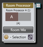
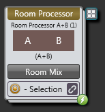
First let’s take a look at The Room Processor block:
At the bottom of the block are a couple of icons that provide quick access to common control links.
The Room Mix button opens up the Room Matrix Mixer where you are able to link to Level controls related to Record Out and Room Out mixes. This is where you want to Link any remote control for controlling a room mix and/or output level. Doing so ensures that the Reference Out tracks the Room Out. While linking to Level controls in the Room Matrix Mixer is a bit more involved than link to a single level control in the standard Room Combine block, it allows a great deal of flexibility.
Let's set up some remote volume controls for Room A, Room B, and Room A+B.
Link to the Room Out Level control in Room Processor A as follows:
Click the Room Mix button for Room Processor A. This opens the Room Matrix Mixer. Create a link between the Room Out level control in the Room Matrix Mixer and a DR1 remote device as by dragging the Room Out link icon to the DR1 (1) link icon as shown in the following image:

You can also access the Room Matrix Mixer from the Room Processor A properties dialog.
After creating this link, do the same in Room Processor B. You now have a DR1 in Room A that controls the volume in Room A and a DR1 in Room B that controls the volume in Room B.
So what happens when you combine the two rooms? Well, at this point, nothing. We haven't configured the Room Processor for Room A+B. Again, think of Room A+B as just another room—a room that doesn't need to know anything about Room A or Room B. With regard to control linking, we simply need to configure the control links we want for Room A+B.
We want the two DR1s to control the volume in the space and to track one another. So we open Room Processor A+B, open its Room Matrix Mixer block properties and create a single control link linking the Level control to both DRs, as shown here: (first link the Room A+B Room Output Level control to DR1 (1). Then add DR1 (2) to the link by clicking on its link icon, dragging it to DR1 (1) and dropping it on its link icon)

It's really as simple as that! Room A+B now has two DR1s that are linked together. When the wall between Rooms A and B is opened (resulting in Room A+B), this control link (along with the other Room Processor configurations for Room A+B) comes off the shelf and is activated.
In summary, creating control links in a room combine situation is no different from creating them in other situations. You simply work with each room one at a time, creating the control links you need for that specific space. When that room is in use, its control links are activated.
Imagine you're the receptionist at a large conference center and you receive an emergency call for a conference attendee named Jonathan Clark. The caller knows that Mr. Clark is currently in Session 3A. You look it up and see that Session 3A is being held in the Flamingo Room. But your current (non-HAL based) paging system has three possible choices for the Flamingo Room—one as a standalone room, one in combination with the Palm Room, and another in combination with both the Palm and Dolphin Rooms. But you haven't a clue as to which walls they've opened or closed! So you page into the standalone Flamingo Room. Unfortunately, you guess wrong. The Flamingo Room has been combined with the other two rooms and the page is heard only in the Flamingo area. Luckily someone else hears it and notifies Mr. Clark that he has an emergency call. What a pain! There must be a better way!
And, of course, there is—the HAL System Conference Room Combine processor way! And guess what? It's automatic. You don't have to do anything—except configure your base rooms. Let's take a closer look.
If you've read about or used the HAL paging system, you know that when you drop a Zone Processor or Paging Zone on your Processing Map, that zone automatically shows up in the Paging Manager and is available to page into. The same is true for base rooms in a room combine. When you add a base room to the Room Combine Processor, that base room appears as a zone in the Paging Manager. When you combine two or more base rooms, their paging zones are merged behind-the-scenes such that a page into any of the combined base rooms is heard in the entire space. Returning to our above example, if using the HAL System, the receptionist's page into the Flamingo Room would be heard in the entire area (Flamingo, Palm, and Dolphin).
Let's take a look. Following is the Room Processor properties dialog box for the combined Flamingo, Palm, and Dolphin rooms (A+B+C). Note that the Paging Zone block shows all three paging zones:

And this is how the three paging zones appear in the Paging Manager:

Paging into any of these zones sends a page to the appropriate output for the currently-active room configuration.
The Distributed Program Bus (DPB) behaves in a room combine just as it does in a Zone Processor. A DPB Selector is available in every Room Processor, regardless of the room combination. Linking this selector control to a remote device such as a DR2 or DR3 gives end users the ability to choose one of the Distributed Program Bus channels, which is then available to be mixed in the To Far End Mixer and the Room Matrix Mixer. In the Room Matrix Mixer, the DPB channel may be independently mixed for the Room Out and Record Out channels.
note: Unlike the standard Room Combine, the DPB selection in the Conference Room Combine may be freely mixed with other signals in the To Far End Mixer and Room Matrix Mixer.
As discussed previously in this topic, each possible room in your room combine has a Room Processor block associated with it. You access these blocks by opening the Room Combine Processor block's properties and then clicking the Room Processors tab. From within a room's Room Processor, you can configure such things as the background music you want, the control links (or other links) that are needed, the volume for the room, the ducker depth and volume of pages, and so on. The Room Processor serves as a mini Processing Map for the room. You cannot drag and drop anything onto the map, but you can set many properties. Anything you customize in the Room Processor pertains to that room and that room only. You do not have to worry about a setting's impact on other room combinations.
If you want to include processing that isn't available in the Room Processor, you can accomplish this by using one or more presets. Each Room Processor comes with its own main preset—and the ability to add more presets. These presets pertain only to the room represented by the Room Processor. When the room is not available (in other words, the wall configuration has resulted in other rooms being active), its presets are deactivated. When the wall configuration changes, making this room active, its configuration comes off the shelf and its presets are activated.
The main preset included in each Room Processor cannot be deleted and is initially empty. When you create a link within the Room Processor, it is added to the preset with an activation state of true. (The link is also added to the Baseline, but with an activation state of false.) You can choose how to work with this main preset, as follows:
- If you want the room to return to its most recent state when it is activated, you should leave the main preset mostly empty (except for control links).
- If you want the room to return to a known state when it is activated, you should save the relevant blocks to the main preset.
Adding a Custom Preset to a Room Processor
Each Room Processor contains, by default, a main preset (a Toggle preset) that cannot be deleted. This preset is activated whenever the room comes off the shelf (in other words, whenever the wall configuration results in the room being in use).
In addition to the main preset, you can create additional custom presets for a specific room. Let's say the room's configuration can change depending on how it is being used (for example, the head table where a panel of speakers is seated may move about depending on the current needs). In this situation, you could create presets for each possible arrangement.
Adding items to a Room Processor preset via drag and drop or updating existing items in the preset using the update buttons can only be performed when the associated Room Processor is currently in use. This restriction is in place to prevent accidental changes to link states that could result in unintended behaviors of linked remotes as room processors are activated or deactivated.
Add a custom preset to a Room Processor as follows:
- In the Processing Map, locate the Room Combine Processor block you want to configure.
- Open the block's properties by double-clicking the block or hovering and clicking the properties icon that appears in the block's title bar, upper right.
- In the properties dialog box, click the Room Processors tab.
- Locate the Room Processor for the room you want to configure, and then open its properties by double-clicking the block or hovering and clicking the properties icon that appears in the block's title bar, upper right.
- In the upper left corner, click Room Presets, which opens a Presets dialog box for presets specific to this room.
- Create your preset(s).
Halogen has two Starter Configurations demonstrating use of the Conference Room Combine block:
- AEC Room Combine Basic
- AEC Room Combine with Room Processing
For more information see Introduction to Conferencing.