AEC (Acoustic Echo Cancellation)
Each EXP7x provides eight AEC parent blocks. AEC blocks appear in the DSP tab under Conferencing. The AEC item is grayed out until an EXP7x expansion device is connected and a user is prompted with the tip (Add EXP7x to Enable). Once an EXP7x is added to the system, the number of available AEC blocks is indicated with the tip (8 Blocks Remaining). As available blocks are used, the remaining number of blocks is indicated. When all available blocks are used, the item is again grayed out and the tip (Add EXP7x to Enable) is displayed.
Other Conferencing blocks that appear under this heading are:
- Switchboard
- Conference Room Combine Processor
- Tracking Compressor
- Tracking ANC (Ambient Noise Compensation)
AEC is required to reduce or eliminate audible echo typically encountered when duplex communication between a near-end and far-end is required. Echo is created when a microphone at a near-end picks up signals from a far-end via a near-end loudspeaker and returns a delayed signal to the far-end, which is then sent back to the near-end. This delayed feedback causes an echo that can impede intelligibility and/or make a system unstable. Transport to and from a far-end may be a short link via copper between conference rooms, greater distance between rooms on a campus via fiber-optic cable or hundreds of miles via a VoIP or POTS connection. An echo may be several milliseconds to a couple of hundred milliseconds depending on the transmission method.
A simplified description of how active AEC accomplishes this task is as follows: First, the AEC algorithm models the room. It does this by comparing a reference signal to what is picked up by the microphone. The model includes everything in the signal path between the AEC Reference and the AEC Local Mic In: local loudspeaker, room acoustics, microphone, etc. Once a room is modeled, an algorithm is able to look at the AEC Reference, estimate what will appear at the AEC Local Mic Input and subtract the estimate from what the microphone picks up. An AEC algorithms ability to remove echo is dependent on the accuracy of its room model.
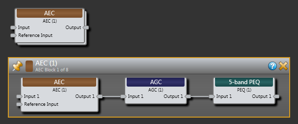
Because the ability to remove echo is dependent on the accuracy of the room model, it is important to avoid unnecessary changes during operation that will vary the relationship between the AEC Reference signal and the AEC Local Mic In. This is why the AEC parent includes AGC and PEQ child blocks after the AEC child block.
See Introduction to Conferencing for more details.
AEC parent and child blocks appear as follows:
- Click the Processing tab to open the Processing Workspace.
- In the palette area, click the DSP tab.
- Expand the Conferencing category of blocks.
- The AEC item is grayed out until an AEC expansion device is connected. If an EXP7x device is not connected, the user is prompted with the tip (Add EXP7x to Enable). See installing and connecting under EXPs heading. Once an EXP7x is added to the system, the number of available AEC blocks is indicated with the tip (8 Blocks Remaining). Click and drag the AEC block into your Processing Map. As available blocks are used, the remaining number of blocks is indicated. When all available blocks are used the item is again grayed out and the tip (Add EXP7x to Enable) is displayed.
- See Introduction to Halogen Conferencing for details on how the block is used in a configuration.
- (Optional) Customize the names of the block and the output node by clicking their current name and then typing the custom name in the text box that appears. Click the X to save the name.
- Open the AEC block's properties by double-clicking the block or hovering and clicking the properties icon that appears in the upper right of the block's title bar. From here, do the following:
- Open individual child blocks by double-clicking a block or hovering and clicking the properties icon that appears in a block's title bar, upper right.
- Configure the Parametric EQ block for conferencing. When setting up the AEC PEQ block for voice, best performance is achieved when low-cut and high-cut filters are set to accommodate voice and no more. This minimizes room noise and provides the clearest signal for the far-end. The five bell filters can be set to “voice” the microphone, but excessive boost and cut should be avoided.
note: For additional information on the functionality and use of the Parametric EQ block, See Parametric EQ Filter
- Configure the AGC block for conferencing. In a conference setup, proper gain structure is an important part of achieving the best signal to noise and intelligibility performance. Setting the Maximum Gain value to high in order to accommodate soft talkers can result in excessive room noise and/or low-level AEC artifacts being sent to the far end. The default values for the AGC provide modest gain below threshold and a ratio of 2.5:1. This provides good operation for most setups. These values can be tailored for your particular application but it’s important to follow a some basic setup guidelines:
Make certain gain is not being applied to room noise when no one is speaking into the microphone. After the gain of the microphone is calibrated and with expected room noise sources active, you can check this by looking at the AGC Gain meter. If the meter is making excursions into the green with no one speaking into the microphone, than the AGC is just amplifying room noise and should be recalibrated. The best way to make this adjustment is to modify the Max Gain value. In conferencing applications, you should use the lowest possible setting. The Ratio control is typically set to control how much louder a signal will get as it moves above the Target value. The Target value is typically set to the nominal signal level when speaking into the microphone or just a bit below.
note: For additional information on the functionality and use of the AGC block: See AGC (Automatic Gain Control)
- Configure the AEC block:
- Little adjustment should be required in the AEC child block.
- The input level controls should not be adjusted during operation. These controls are provided as a convenience for systems designers but typically left set to unity gain.
- NLP is set to 20% by default. This setting works well for most applications. Higher settings reduce more echo artifacts but may interfere with double talk. Lower settings do not improve double talk much but may result in more AEC artifacts.
- AEC Threshold set the level below which the AEC function is bypassed. This eliminates AEC artifacts when a mic is gated off. The threshold should be set so that the AEC Threshold LED is off when a Mic is muted.
- Ambient Noise Reduction should be on. The default setting of 6 dB results in optimum performance in a typical conference room. If a room is very noisy, higher settings can be more appropriate. Note that settings much above 10 can have some detrimental side effects such as some ducking of speech and low level distortion.
note: For details about AEC see Introduction to Conferencing
| UI Element | Purpose |
|---|---|
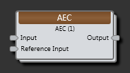
| Input node | Connection point for wiring a near-end microphone input to the AEC block. |
| Reference Input node | Connection point for wiring the room AEC reference input. |
| Output node | Connection point for wiring the AEC output signal. This signal will have reduced echo and ambient noise with AGC and PEQ processing applied. This is the signal required to send to the far-end. |
| UI Element | Purpose |
|---|---|
|
Input meter Input Gain Reference meter Ref Gain |
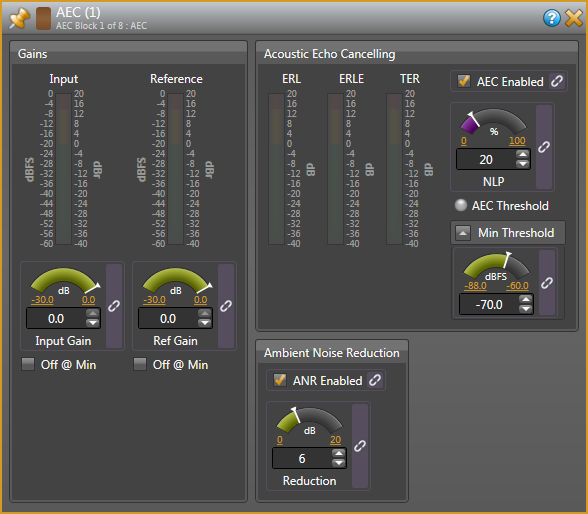
Input meters and Gain controls are provided for microphone and reference inputs. Input Gain (MIC) and Ref Gain controls are used to adjust the Input and Reference so that signal levels are about 0 dBr on the meters in the presence of normal speech and room audio. While these Gain controls may be linked, they should not be adjusted during operation as this will adversely affect AEC operation. If all other settings are correct, these controls may be left set to unity gain. |
|
ERL meter ERLE meter TER meter |
There are three AEC meters, ERL, ERLE and TER. The ERL meter provides an indication of how well echo is suppressed based on room acoustics: microphone type, placement/sensitivity and loudspeaker location/loudness. While the AEC block is able to work well with little or no acoustic echo suppression, the more acoustic suppression a designer is able to realize, the better active AEC will work without adding any artifacts. A reading of -8 dB indicates 8 dB of echo suppression. The ERLE meter provides an indication of how much additional echo suppression is being achieved by active acoustic echo cancellation. A reading of -20 dB indicates 20 dB of additional echo suppression. The TER meter is just a convenient way for a system designer to see what the total echo reduction is without having to add ERL and ERLE. |
| AEC Enable | AEC Enable allows AEC to be enabled or disabled. Checking the box enables AEC operation. This control is useful for A/B comparison of performance with and without active echo cancellation. When AEC is not enabled an acoustic model of the room is still acquired and maintained. |
| NLP |
The NLP control adjusts the level of nonlinear processing performed by the AEC block. Primary echo cancellation is accomplished with linear processing where a room is modeled, echo estimated and subtracted from the signal pick up by the microphone. Nonlinear processing deals more with random, lower-level reflections and nonlinearities that the model does not deal with as well. NLP is adjustable as its operation needs to strike a balance between reducing nonlinear echo components and generating unwanted artifacts and adversely affecting double-talk. While this control is linkable, its value should be set by the system designer and it should not be adjusted during operation. Good performance is typically achieved with a setting of 20% to 50%. |
| AEC Threshold |
The AEC Threshold indicator lights when AEC is active. Threshold is typically set so be off only when a microphone is muted. |
| Min Threshold | The Min Threshold control allows a system designer to set the minimum signal level picked by the microphone that will enable the AEC algorithm and allow it to model a room and apply active acoustic echo cancellation. When a microphone becomes inactive, this prevents the algorithm from diverging from a good room model acquired while the microphone was active or acquiring and inaccurate model before a microphone is active. While linkable, this control should be set by the system designer as part of system calibration and should not be adjusted during operation. |
| ANR Enabled | The Halogen AEC block includes Ambient Noise Reduction (ANR). The ANR Enable control allows ANR to be enabled or disabled. ANR is enabled when the box is checked. |
| Reduction |
The ANR Reduction control lets the system designer set the level of ambient noise reduction from 0 dB to 20 dB. Ambient noise includes any relatively constant noise source in the room such as fan noise from a projector. The algorithm also suppresses howling. The control is typically set to adequately reduce steady background noise while still sounding natural. Settings of 6 to 10 dB are typical. |
 See Also