Overview of Remote Audio Devices
The primary purpose of a Remote Audio Device (RAD) is to amplify, digitize, and transmit a digital audio signal via shielded CAT 5e cable to a HAL host device. RADs can also receive a digital signal from the HAL and then convert it to analog before sending it to its attached audio equipment. RADs are capable of transmitting and receiving up to four channels of digital audio (two in each direction). To better fit your needs, however, Rane offers various RAD models. Most RAD models are designed to fit in a standard U.S. two, three, or four gang switchbox.
The HAL System offers a variety of RAD models, each of which serves a unique purpose. For example, a RAD1 contains two microphone input channels. When you design an audio system, you choose the RAD models that are appropriate for your application. You must then provide configuration information to HAL so that it knows which RAD models to expect on each port and what information to send to each RAD. For more information,
The shielded CAT 5e cable that connects the RAD to HAL also provides power to the RAD as well as a path for data communications. Data communications makes it possible to control the RAD’s configuration settings, view status information, and update a RAD’s firmware – all from the host HAL device. The following picture illustrates how the four twisted pairs within the shielded CAT 5e cable are utilized.
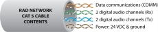
- The orange pair is reserved for data communications between the RAD and HAL. Data communications is needed for such things as sending configuration information from HAL to the RAD, sending firmware updates from HAL to the RAD, and sending status information from the RAD to HAL.
note: Configuration information for a specific RAD (for example, LED intensity, microphone sensitivity, and RAD and channel names) is stored in the HAL device, not in the RAD. This makes it easy to swap in a new RAD, if necessary, without losing configuration data.
- The green and blue pairs carry two channels each of balanced, differential, digital audio. Tx refers to audio that the RAD sends to the HAL. Rx refers to audio that the RAD receives from HAL.
- The brown pair provides 24 VDC power and ground for the RAD. This is (obviously) the wire you should check if it appears a RAD is not receiving power.
note: Digital Remotes use only the orange pair (for data communications) and the brown pair (for power).
RAD Grounding
note: For some electrical systems (e.g., isolated grounding systems - sometimes called a single point or star ground) the grounding procedure outlined above may short two fingers of the building ground system. If this creates a problem, then use of non-conductive junction boxes, or insulating mounting methods are recommended (or very much required!).
note: The RAD16z is grounded differently than the above. The RAD16z galvanicaly isolates its RJ-45 jack, cable shield and grounded twist, and the HAL/equipment room ground from its logic and audio I/O grounds. This means no special ground is needed. This provides 500-volts galvanic isolation as well as standard Ethernet-like electrostatic protection as the RAD16z cables get hot plugged and unplugged.
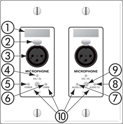
Following is an illustration of the front of a typical RAD. Click each number to see a description of the associated RAD part.
Following is an illustration of the back and side of a typical RAD:
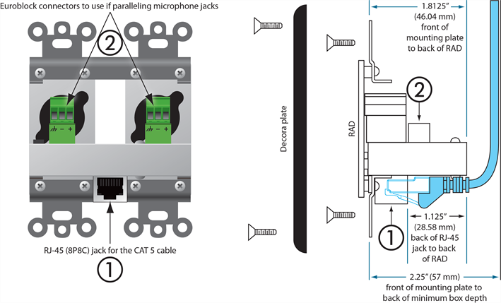
warning! As it is poor design to plug two microphones into a single microphone input, we do not recommend this practice.
note: RADs are hot-swappable. In other words, you can replace a RAD without having to power down the system. The HAL automatically detects the new RAD and configures it using the configuration data stored in the HAL. If the configured RAD and the physical RAD do not match, the HAL front panel Enabled LEDs for this RAD flash yellow. At the same time, the RAD's Power, Comm, Audio Rx, and Audio Tx LEDs flash red.
- Generating RAD Labels
To generate RAD labels:
- Within Halogen, open the configuration file from which you want to generate labels. Alternatively, if you have applied the configuration to a HAL device, you can open the device itself.
- In the Hardware Workspace, confirm that the RADs are configured appropriately. At a minimum, enter the names for the channels as this is needed for the generation of labels.
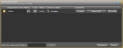
- In the Hardware Workspace toolbar, click Generate Labels :
 The Generate Device Labels dialog box displays.
 - In Name and Location, browse for or type the location and file name you want for the PDF file you are generating. If you type the name of a folder that does not exist, the software will create it for you. By default, the file is named
DeviceLabels.pdfand is placed inC:\Users\<user>\Documents\HalogenLabels,although this location may vary depending on your operating system. - In Label Color, select the color you want your labels to be (to match the RADs you will be using). The choices are white (with black text), black (with white text), and ivory (with black text).
- Click Create. Halogen generates the PDF file and, once it is complete, enables the View button.
- Click View to open the file.
- When you are satisfied with the results, print the PDF file. It is best to use 24# paper.
- Cut out the labels and insert them behind the Lexan window on the appropriate RADs. To help with the alignment of the labels, we recommend that you wait until after inserting the labels before trimming off the excess paper (using an Exacto or box knife).
note: If you want to use different fonts or colors for the label text, you will need to create the label document yourself. To do so, download the Microsoft Word template from the Rane website. Enter the channel names, apply the appropriate fonts and/or colors, print the document, and cut and insert the labels.
- Locating a RAD
To locate a RAD:
-
Connect to the HAL device.
- From the Device menu in the application toolbar, click Connect
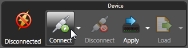
- In the Connect to Device dialog box that appears, find the HAL device you want
- Click the Connect button associated with that HAL device.
- From the Device menu in the application toolbar, click Connect
-
Click the Hardware tab to open the Hardware Workspace.
- In the Hardware Workspace, click the Locate button associated with the RAD you want to identify:
 See Also