Connections between Expansion Units (EXPs), Remote Audio Devices (RADs) and Digital Remotes (DRs) all have the same cable requirements: Shielded CAT 5e or better. This section includes more details about the CAT 5e cable requirements, including recommended cable type, maximum lengths, and proper termination.
Cable Type
The HAL System wiring complies with the standard shielded CAT 5e T568-A or T568-B termination. You can use a shielded CAT 5e, or a CAT 6 cable (UTP-plus overall shield with drain wire and 24 AWG). To comply with the FCC and European emissions standards, you must use cable for all EXP, DR and RAD devices that has screened twisted pairs (four unshielded twisted pairs surrounded by a single foil shield with a drain wire). This is variously referred to as either F/UTP, S/UTP, FTP, and ScTP. An example is Belden 1212F.
You'll also sometimes see the term STP, although technically this refers to individually-shielded twisted pairs. For the remainder of this guide, we'll be using the term shielded CAT 5e to represent all of these choices.
|
Device |
Meters |
Feet |
|---|---|---|
|
EXP |
100 | 300 |
| RAD | 150 | 500 |
| DR | 300 | 1000 |
Terminating the shielded CAT 5e Cable
When terminating the cable, it is important to maintain the natural twist of each wire pair as close to the termination as possible. Use a standard shielded RJ-45 connector to terminate the cable. Note that outputs are short-circuit protected.
note: Here is a bit of trivia for you. What are commonly referred to as RJ-45 jacks are not RJ-45 at all but are 8P8C (8 Position 8 Contact) modular connectors. We’ll bow to convention, however, and use the more recognized term of RJ-45.
RAD and DR Grounding
note: For some electrical systems (e.g., isolated grounding systems - sometimes called a single point or star ground) the grounding procedure outlined above may short two fingers of the building ground system. If this creates a problem, then use of non-conductive junction boxes, or insulating mounting methods are recommended (or very much required!).
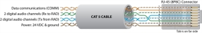
The following graphic illustrates the T568-B termination and also shows the function of each wire pair on the RAD/DR network:
 See Also