Matrix Mixer
The Matrix Mixer block mixes multiple input signals into a variety of output channels.
note: You may be wondering if you'll need to use the Matrix Mixer block to set up paging, complex zoning, and room combine. The answer is an emphatic NO! Most systems (including Rane’s DragNet products) use matrix mixers for these applications. Perhaps you are familiar with the complex features of the RPM’s Mixer/Router/Ducker block. Matrix mixers (along with presets) have historically been the Swiss Army Knife of audio DSP (if your Swiss Army Knife contained 256 identical blades). Zoning, paging, and room combine required a giant matrix with inputs for every background music source, paging station, microphone, and line input in the system. Developing the audio system involved taking snapshots of the matrix mixer as configured for every possible permutation of background music selection, room combination, and page source to destination. As the number of inputs, zones, and configurable walls increased, the number of crosspoints in the matrix and presets in the system grew exponentially. The HAL System removes this burden by providing more powerful blocks and subsystems that are already programmed with the logic required to perform complex paging, zoning, and room combine processing. If you’re designing a powerful, modern audio system, leave that Swiss Army Knife in your pocket and take a look at the Zone Processor, Room Combine Processor, Distributed Program Bus, Paging Station and Paging Zone blocks. These blocks will get you much farther in a fraction of the time.
Use the Matrix Mixer block to mix multiple input signals into a variety of output channels.
- Click the Processing tab to open the Processing Workspace.
- In the palette area, click the DSP tab.
- Expand the Mixers category of blocks.
- Click and drag the Matrix Mixer block into your Processing Map.
- Wire it into your system in the appropriate location. If you need additional inputs or outputs, simply wire to the <Add> node or click the <Add> text.
- (Optional) Customize the names of the block and/or the input and output channels by clicking their current name and then typing the custom name in the text box that appears. Click the X to save the name.
- Open the Matrix Mixer block's properties by double-clicking the block or hovering and clicking the properties icon that appears in the upper right of the block's title bar. The properties dialog box displays up to four input channels across the bottom of the dialog, and four output channels down the right side of the dialog. Use the scroll bars (located beneath the inputs and to the right of the outputs) to bring other inputs/outputs into view. The grid formed between the inputs and outputs is called the matrix. Each square in the matrix (where an input column and output row intersect) is called a crosspoint.
- Enable inputs by ensuring that the channel is unmuted. Each input channel includes both a Signal presence indicator and a Mute control that can mute the input so that it is silenced in all outputs.
- For each output, decide which inputs you want mixed into that output channel. Notice that each crosspoint includes an Enable checkbox and a level control. These two parameters determine whether and at what level the crosspoint’s input is mixed into the crosspoint’s output. All the crosspoint audio for a row is sent to the output level and meter for that row. In each row, select the Enable checkbox for each input to include in the mix.
- Control the mix volume. Use the output level and meter to set the output volume to your system’s nominal signal level (typically, -20 dBFS). To mute the mix output without changing the output level control, select the output's Mute checkbox.
- Provide end user control over the input mutes, crosspoint levels or enable state, or output level or mute by linking those controls to the corresponding controls on one or more DRs. For example, if you are using the Matrix Mixer for simple zoning, and the end user wants control over output volumes, add a DR3 to your system and configure it to behave as a list of levels. Add a DR3 level control to the DR3 for each output from the matrix mixer. Link each DR3 level to an output level on the matrix mixer. If you want to limit the range of end-user output volume control, adjust the Min and Max settings of the output levels. Selecting the Off @ Min checkbox at the mixer output will mute the output when the level control reaches its minimum value. Therefore, the end user could have 12 dB of level control with output completely muted when the level control is dialed all the way down.
From this dialog box, you can do the following:
note: These signal indicators are actually meters, therefore they are subject to the same 16 active meter limit as all other meters.
| UI Element | Purpose |
|---|---|
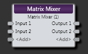
| Input nodes | Connection points for wiring input to the Matrix Mixer block |
| Output nodes | Connection points for wiring the Matrix Mixer input to specific outputs |
| <Add> nodes | Click to add another Input or Output node, or wire to the <Add> node to automatically create a new channel. |
(Hover over the thumbnail below to view the properties dialog box.)

| UI Element | Purpose |
|---|---|
| Crosspoint | Each square in the matrix where an input column and output row intersect |
|
Crosspoint Level (Manual and Linkable Control) |
Control the relative volume of an input signal. Each input is attenuated by the level of the control in the input column and then they are all summed together before reaching the output level. Provide end users with control over input volume by linking this Level Control to the Level Control of a DR1 or DR3. |
| Crosspoint Enable Checkbox | Select to include the input in the mix. |
| Input Mute (Manual and Linkable Control) | Mute this input. Provide end users with mute control by linking this Toggle Control to the Toggle Control of a DR2, DR3, or Logic In. |
| Input Signal | Lights when a signal is detected on this input, turns red if signal overload occurs. |
| Output Level (Manual and Linkable Control) | Control the volume of the entire mix for that output. Provide end users with control over the output volume by linking this Level Control to the Level Control of a DR1 or DR3. Change the range by clicking the Minimum or Maximum value (below the slider) and then typing new values in the edit box that appears. |
| Output Mute (Manual and Linkable Control) | Mute the mix output without changing the output level control. Provide end users with output mute control by linking this Toggle Control to the Toggle Control of a DR2, DR3, or Logic In. |
| Output Off @ Min Checkbox | When checked, causes the audio to mute completely when dialed to the low end of its range. |
| Overall Mute Checkbox | Mute all outputs from the Matrix Mixer block. Manual control only. |
 See Also