Room Combine Processor
The HAL System Room Combine Processor is designed to simplify the task of configuring the audio system for a set of rooms containing movable walls that can be opened and closed in a variety of ways (configurations that are common in hotels, churches, schools, and conference centers). It is also perfectly suited for meeting rooms that do not combine since it makes paging and background music feeds into such rooms automatic and easy.
For more details on the Room Combine Processor's functionality, see About Room Combine.
Included here is basic information for adding a Room Combine Processor block to your system. For more details about working with the Room Combine Processor, including detailed procedures and example scenarios, see Room Combine.
- Click the Processing tab to open the Processing Workspace.
- In the palette area, click the DSP tab.
- Expand the Paging/Room Combine category of blocks.
- Click and drag the Room Combine Processor block into your Processing Map.
- Adjust the number of base rooms needed for your room combine (by deleting or adding rooms).
- Wire microphone and line inputs to each base room and, if necessary, add a cascading automixer such as an AM2.
- Wire each base room's outputs as appropriate.
- (Optional) Create custom names for miscellaneous items on the block: the block name, input names, output names, and paging zone names.
For a more detailed discussion of this procedure, see Adding a Room Combine Processor to the Processing Map.
- Open the Room Combine Processor block's properties by double-clicking the block or hovering and clicking the properties icon that appears in the upper right of the block's title bar. From here you can do the following:
- Configure the physical layout of the rooms, specify which common walls are movable or overflow, and provide end users with control over which walls are open or closed. For details, see Configuring Layout and Control of Room Configurations.
- Access the individual Room Processor blocks for each possible room, from which you can configure a wide variety of parameters, create additional control links specific to that room, and customize the room's main preset or add other presets. For more details, see Room Processor as well as Configuring a Room Processor.

| UI Element | Purpose |
|---|---|
| Distributed Program Bus flag | Represents the automatic inclusion of the Distributed Program Bus channels |
| Auto Mixer |
Connection point for wiring local microphone input to a Base Room Click <Add> to add another Mic In node, or wire a Mic input directly to the <Add> node to automatically create a new node. Use the <Add Cascade In> flag to cascade in another Auto Mixer (specifically, the AM2 RAD). To add the AM2, drag it from the I/O tab (after adding it in the Hardware Workspace) and drop it on the flag. You can cascade multiple AM2s. Each time you add one, another flag appears, ready to accept the next AM2. |
| Mixer |
Connection point for wiring local line input to a Base Room Click <Add> to add another Line In node, or wire a Line input directly to the <Add> node to automatically create a new channel. |
| Record Out and Room Out nodes | Connection point for wiring the room's audio to a specific output. Record Out is intended for routing output for recording or assisted listening purposes, or overflowing room audio to another zone that contains its own volume control and paging zone. The Record Out node sends pre-level and pre-page output to its destination—thus avoiding room volume changes or page interruptions from being recorded. Room Out is the output you want reinforced in the room. |
| Zone flag | Represents the room's paging zone (and automatic connection to the paging system) |
| Add Room button |
Add another base room to the block. You can have a total of 12 base rooms in a single Room Combine Processor block. To delete a base room, click the red X in the lower right corner of the room. |


| UI Element | Purpose |
|---|---|
| Layout & Control tab |
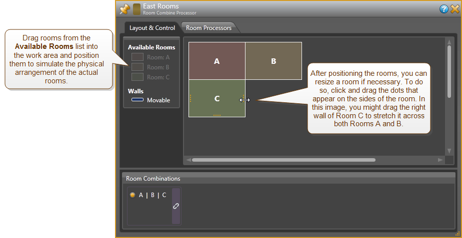
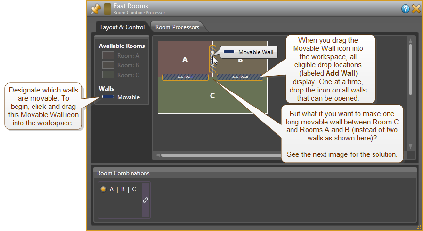
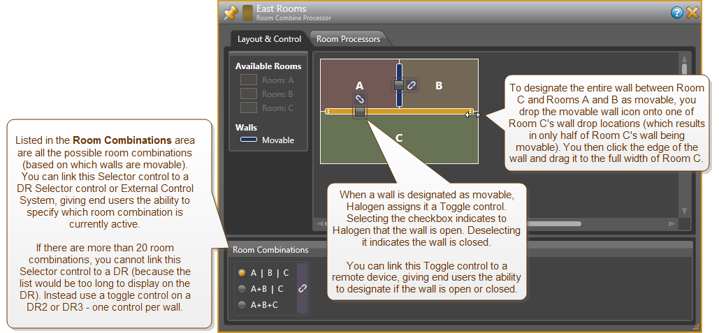
Use this tab to arrange the base rooms in the proper physical layout, to specify which walls are movable, and to create control links that give end users a way to indicate which walls are open or closed. When first opened, help text appears in the Layout work area providing guidance on how to get started. See below for a more detailed description of the Layout & Control tab. |
| Room Processors tab |
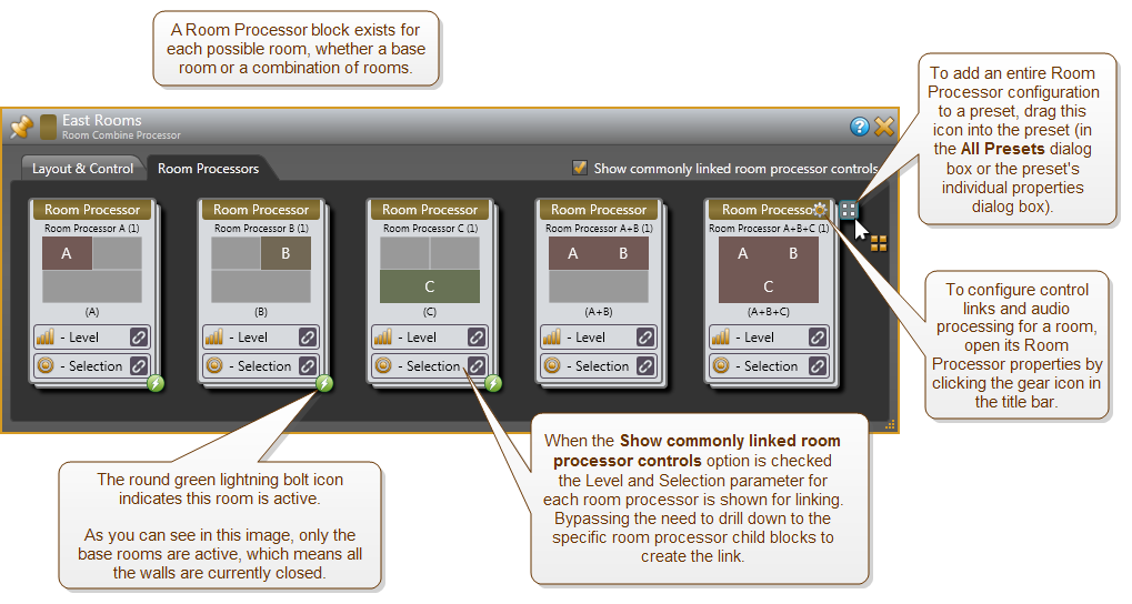
This tab contains the Room Processor blocks for each possible room—base rooms as well as combined rooms. To customize the audio processing for a room, open its Room Processor properties and configure from there. To customize the control links for a room, enable the Show commonly linked room processor controls option and configure directly from the room processor block, or open the Room Processor properties and configure from there. See below for a more detailed description of the Room Processors tab. |
For more details, see the Room Processor reference topic.
 See Also