More Complex Room Combine with Custom Presets and Cascaded Automixer(s)
This room combine example is slightly more complex than the two-room example. It contains three rooms, which results in more room combinations. By itself, this fact doesn't make this scenario more complex - it just means there are more Room Processors to configure. What does make this scenario more complex, however, is its use of custom presets and the inclusion of cascaded automixers. But don't let that word complex fool you! It's still amazingly simple!
This three-room room combine is in a hotel conference center. Each base room (depending on its size) contains one or two loudspeakers, one or two mic and line inputs (RAD2s), and one or two remote controls for source selection and volume control (DR3s). When the three rooms are combined, it is often because of a large presentation featuring many human speakers. Therefore, a portable automixer is needed to bring in additional microphones and include them in the gain-sharing mix. There also needs to be flexibility in the location of the head table during such presentations - specifically being able to place the head table on the east wall or on the west wall, depending on the presenters' wishes. To prevent feedback and optimize the audio for the audience, the output level for the loudspeaker closest to the head table is reduced by 3 dB. In addition, to prevent audience members from accidentally adjusting volume or changing audio selections, the DRs in other areas of the room (away from the head table) are disabled. The largest room contains a DR2 (for selecting the appropriate Head Table preset).
The basics of configuring a room combine are detailed in the two room scenario, so we'll skip many of the details covered in that example.
- In the Hardware Workspace, add and configure the following hardware devices:
- 4 RAD2s
- 2 AM2s (depending on the HAL device model, may need an EXP1 to accommodate these two RADs)
- 4 DR3s (configured as Single Level & Selector)
- 1 DR2 (configured as Single Selector)
- In the Processing Workspace palette, click the DSP tab.
- In the Paging/Room Combine category, click and drag a Room Combine Processor into the Processing Map. Drop it wherever you like. We'll be using all three rooms that are there by default, so there is no need to add or delete base rooms.
- Wire inputs to the three rooms, as follows:
- Room A
- RAD2 Mic Input wired to Room A's Auto Mixer
- RAD2 Line Input wired to Room A's Mixer
- Room B
- RAD2 Mic Input wired to Room B's Auto Mixer
- RAD2 Line Input wired to Room B's Mixer
- Room C
- Two RAD2 Mic Inputs wired to Room C's Auto Mixer
- Two RAD2 Line Inputs wired to Room C's Mixer
- Two AM2s cascaded into Room C's Auto Mixer (Drop each AM2 on the available <Add Cascade In> flag.)
- Room A
- Wire the output from each room to a PEQ block and then to a HAL Line Output block. Note that Room C's output is wired to two loudspeakers, thus two PEQ blocks and two Line Output blocks. Here's what we have thus far:

- Configure the layout of the rooms and specify which walls are movable.
- Open the Room Combine Processor's properties by double-clicking the block or hovering and clicking the properties icon that appears in the upper right of the block's title bar.
- In the Layout & Control tab, drag Room A into the work area. Drag Room B into the work area and place it directly beside Room A. Now drag Room C into the work area and place it below Room A. Expand it to cover both Rooms A and B:

- In the Available Rooms area, click and drag the Movable icon into the work area. Notice that Add Wall appears on all common walls. Drop the Movable Wall icon on the wall between Rooms A and B:
 Repeat the process and drop the icon on the wall between Room A and Room C. Then expand the movable wall across all of Room C (because the wall is either all the way open or all the way closed). To expand the wall, click and drag the edge of the wall:
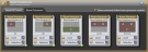
Halogen has calculated the number of possible room combinations (three), resulting in five possible rooms:
- At this point, you would configure the Room Processors for each room. This scenario is focused on what happens when all three rooms are combined, so we'll skip the Room Processor configuration for all the other rooms. Instead, we'll summarize how each base room is configured. Keep in mind, however, that these base room configurations have no impact on the configuration of any combined rooms. We're providing this information just to give you a better idea of the entire scenario:
- Room A
- Contains a control link between the room's Level control and the Level control on the DR3 located in the room.
- Contains a control link between the room's Selector control and the Selector control on the DR3 located in the room. There are two selections: the Distributed Program Bus channel (a commercial music channel) and the local audio input.
note: When these control links are created, they are automatically saved to the Room A Room Processor's main preset.
- Room B
- Contains a control link between the room's Level control and the Level control on the DR3 located in the room.
- Contains a control link between the room's Selector control and the Selector control on the DR3 located in the room. There are two selections: the Distributed Program Bus channel (a commercial music channel) and the local audio input.
note: When these control links are created, they are automatically saved to the Room B Room Processor's main preset.
- Room C
- Contains two DR3s, each configured as follows:
- Contains a control link between the room's Level control and the Level control on the DR3.
- Contains a control link between the room's Selector control and the Selector control on the DR3. There are two selections: the Distributed Program Bus channel (a commercial music channel) and the local audio input.
- Contains a DR2 configured as a Selector. We will link the Selector control to the Selector presets we are about to create.
note: When these control links are created, they are automatically saved to the Room C Room Processor's main preset.
- Contains two DR3s, each configured as follows:
- Room A
Configuring Presets for Room A+B+C
- We'll now get to the meat of this scenario—working with presets in a room combine situation. To do so, we'll jump to the configuration of the A+B+C room. When this room is in use (in other words, all the walls are open), it is usually because a large audience is expected. Quite often the presentation taking place involves multiple presenters seated at a head table. We want to configure the room so that placement of the head table is flexible. It can be on the east wall or on the west wall. There are various parameters and controls we want to adjust whenever Room A+B+C is activated. We add these adjustments to the room's main preset. There are other parameters and controls we want to adjust for each head table location. We add these to custom presets we create for this room. Let's start with the room's main preset.
- When all the walls are open, we want the Room C DR3s to control the volume and selection control. Create these control links as follows:
- Open the room's Selector block and link its Selector control with the Selector control of each Room C DR3.
- Open the room's Level block and link its Level control with the Level control of each Room C DR3.
- Next, we will save some custom settings to the room's main preset, which is the default preset that is automatically created and cannot be deleted. To view the main preset, click Room Presets in the upper left corner:
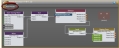 The All Presets dialog box (for Room A+B+C) opens, displaying the room's default Toggle preset. Click the preset name to open it and view its contents:
  As you can see, it already contains the control links we created in the previous step. We now want to add a few custom settings:
- PEQ settings specific to this A+B+C room
- Disable the DR3s located in the Room A and Room B areas of Room A+B+C. They are not needed, and disabling them guarantees they cannot be adjusted by anyone.
- Enable the DR2 located in the Room C area of Room A+B+C. This DR2 will provide control over which head table preset is active.
You add these items to the main preset just as you would to any preset (see About Presets):
- Adjust the PEQ settings to fit the acoustics of the larger space, and then add the PEQ blocks to the room's main preset:


- Disable the Room A and Room B DR3 controls by opening each control (click the control name in the Control tab in the Processing palette), deselecting the control's Enabled checkbox, and then saving the control to the main preset:

- Follow the same procedure to enable the DR2 located in the Room C area of Room A+B+C (with the exception that this time you are selecting the Enable checkbox instead of deselecting it!).
- We will now create two custom presets for Room A+B+C—one for positioning the head table on the east wall, and one for positioning the head table on the west wall. Each preset will contain the following settings:
- To prevent feedback and optimize the audio for the presenter and audience members, the output level closest to the head table will be set 3 dB lower than the output level furthest from the head table.
- To prevent someone other than a presenter from adjusting the volume in the room, the DR3 on the opposite wall from the head table will be disabled.
- To guarantee that no other input is available other than the audio from the head table, mute all RAD2 inputs other than the one being used by the presenters.
To create these presets and add blocks and controls to them, do the following:
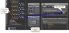
- Open the Room A+B+C Room Processor properties, and then click the Room Presets button in the upper left corner. In the All Presets dialog box that displays, click the Selector tab. We are creating a Selector preset because the two preset options (Head Table East, Head Table West) are mutually-exclusive. Click the +Selector button to create a new Selector group, and then click +Preset twice to add two presets to the group. Name them Head Table East and Head Table West. Select the Head Table East radio button and uncheck Include 'No Selection':

- We'll now configure the Head Table East preset, beginning with the level offset for the loudspeakers closest to the head table - in this case the loudspeakers on the east side of A+B+C. To do, locate the output blocks for the loudspeakers on the east wall of Room A+B+C. Open each block's properties and set the Gain to -3.0 dB. Add the Output blocks to the Head Table East preset. It looks something like this:

- Disable the controls on the Room C DR3 that is on the opposite wall from the head table (in this case, the west wall), and then add the controls to the Head Table East preset:
- Mute all the RAD2 inputs other than those on the east wall near the head table:
 Add the muted RAD2 input blocks to the Head Table East preset:
- Create the Head Table West preset.
- The final step is to link this new Selector Preset Group to the DR2 from which end users will select the preset to apply: Head Table East, or Head Table West:
 The resulting DR2 properties then look something like this:
The first step is to open the Room Processor properties for Room A+B+C. To do so, click the Room Processors tab, and then open the properties for Room Processor A+B+C: 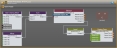
 See Also
- About Conference Room Combine
- About Room Combine
- Adding a Custom Preset to a Room Processor
- Adding a Room Combine Processor to the Processing Map
- Arranging the Base Rooms and Walls
- Configuring Individual Room Processors
- Configuring Remote Control of the Room Configuration
- More Complex Room Combine with Custom Presets and Cascaded Automixer(s)
- Simple Two-Room Room Combine