Simple Two-Room Room Combine
This room combine example is as simple as it gets—combining two rooms. For purposes of this scenario, let's assume that these two rooms are in a hotel conference center. There is a common, movable wall between the two rooms. When closed, the individual rooms are typically used for presentations to relatively small audiences. For larger audiences, the wall between the rooms is opened. Each base room contains two mic inputs (RAD1), two line inputs (RAD3), and a DR3 (to control source selection and volume in the room). In the back room is a DR2 that will give end users the ability to specify the room configuration currently in use.
The hotel has a paging system (using PAGER1 devices) and also uses a commercial music channel to provide background music in all its zones.
The name of Room A is Wisteria. The name of Room B is Magnolia.
note: Because the focus of this scenario is room combine, we will skip details of the configuration of the paging system and the Distributed Program Bus (for the commercial music channel). These topics are covered elsewhere in this help system.
- In the Processing Workspace palette, click the DSP tab.
- In the Paging/Room Combine category, click and drag a Room Combine Processor into the Processing Map. Drop it wherever you like.
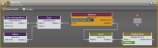
- Delete Room C by clicking the red X located in the lower right corner of that room:

- Wire inputs to Room A and Room B.
- In the palette, click the I/O tab, and drag the RAD1 and RAD3 channels into the Processing Map.
- Wire one of the RAD1's Mic Input channels to Room A's Auto Mixer, and the other RAD1's channels to Room B's Auto Mixer. Wire one of the RAD3's Line Input channels to Room A's Mixer, and the other RAD3's Line Input channels to Room B's Mixer:

- Customize the name of the paging zone for each room. To do so, click the name in each green zone flag and type the new name in the edit box that appears:

- Wire the room outputs to the appropriate processing and/or output blocks.
- Configure the layout of the rooms and specify what wall is movable.
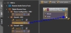
- Open the Room Combine Processor's properties by double-clicking the block or hovering and clicking the properties icon that appears in the upper right of the block's title bar.
- In the Layout & Control tab, drag Room A into the work area. Drag Room B into the work area and place it directly below Room A:

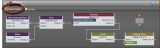
- In the Available Rooms area, click and drag the Movable icon into the work area. Notice that an Add Wall area appears where Room A and Room B connect. Drop the Movable Wall icon onto the Add Wall area:

Now notice that Halogen has calculated the number of possible room combinations. In this case, there are two possibilities: two separate rooms, or one big room:

- Provide end users with control over what room configuration is currently active. Because there are only two choices, it is okay in this scenario to use the Selector control showing the possible room configurations. (If there were more than 20 choices, you could not use the Selector control. You would need to expose the Toggle controls on each wall instead.) We could use the Toggle controls in this case as well, but we'll opt for the Selector control.
- In the Processing Workspace palette, click the Control tab.
- Locate the DR2 Selector control and link it to the Room Combinations Selector control:

warning! Once you have linked the Room Combinations Selector control, you cannot make changes to the room and wall layout. If changes are needed, you would have to remove the Selector control link, make your changes, and then re-link the Selector control.
- Configure control links and processing for each possible room.
- Click the Room Combine Processor's Room Processors tab to display the Room Processor blocks for each possible room. We'll begin by configuring Room A (the Wisteria Room). Note that you can rename the Room Processor by clicking its current name and then typing a custom name in the edit box that appears. In this case we've renamed them to Wisteria, Magnolia, and Combined.

- Open Room A's Room Processor properties by double-clicking the block or hovering and clicking the properties icon that appears in the upper right of the block's title bar.
- For this simple example, we'll assume that the Gain-sharing Mixer and Mixer need no additional configuration. We'll go straight to setting up our control links. As mentioned, the hotel subscribes to a commercial music channel for background music. This channel has been included in the Distributed Program Bus and is, therefore, available in the Wisteria Room. So we need to provide end users with selection control so they can choose between background music or the audio local to the room. To configure this control link, we must first open the Room Processor's Selector block properties:

- The end user also needs control over the volume in the Wisteria Room, so we'll link the room's Level control to the DR3's Level control. To do so, we first open the room's Level properties:

Now, let's link this Selector control to the Selector control on the DR3 in the Wisteria Room (Room A). To do so, click the Control tab in the Processing Workspace palette, and locate Room A's DR3. Create a control link between its Selector control and Room A's Selector control:
Now, let's link this Level control to the Level control on the DR3 in the Wisteria Room (Room A):

End users can now use the room's DR3 to select the audio and adjust its volume.
note: The two links we have just created (Selector link and Level link) are stored in Room A's main preset. To view this preset, click the Room Presets icon in the upper left corner of Room A's Room Processor properties dialog box:
- If desired, you could configure other parameters in the Room Processor's blocks. You could also provide end users with control over the page volume by linking the Paging Zone's Level control to a DR.
- To complete your configuration for this room combine, you would now move to the Room Processors for the Magnolia Room (Room B) and the combined room (Wisteria (A) + Magnolia (B)). Remember that each of these rooms are configured and treated as completely separate from one another. The configuration we have just completed for the Wisteria Room is unique to that room and does not impact the other rooms. To illustrate this point, when you open the Room Processor for the combined room (Wisteria + Magnolia), notice that the control links we just configured for Wisteria are not there. That's because Wisteria is a completely different room from Wisteria + Magnolia.
- Click the Room Combine Processor's Room Processors tab to display the Room Processor blocks for each possible room. We'll begin by configuring Room A (the Wisteria Room). Note that you can rename the Room Processor by clicking its current name and then typing a custom name in the edit box that appears. In this case we've renamed them to Wisteria, Magnolia, and Combined.
- Test your room combine configurations.
- After completing your configuration of each Room Processor, you should test that the control links and block configurations work properly when the wall is opened and when it is closed. To test this, simply toggle the wall control (in the Layout & Control tab) to simulate an open wall and then a closed wall, and double-check that the correct configuration is in place for each situation.
 See Also
- About Conference Room Combine
- About Room Combine
- Adding a Custom Preset to a Room Processor
- Adding a Room Combine Processor to the Processing Map
- Arranging the Base Rooms and Walls
- Configuring Individual Room Processors
- Configuring Remote Control of the Room Configuration
- More Complex Room Combine with Custom Presets and Cascaded Automixer(s)
- Simple Two-Room Room Combine