This
- Are you creating links that connect only one control to another, with each control participating in only one link? You'll find everything you need in Basics of Control Linking. Reviewing the Best Practices section is also a good idea, but you can skip Advanced Topics.
- Are you creating links that connect three or more controls? You should review Basics of Control Linking, Advanced Topics, and Best Practices (in other words, read everything!).
Basics of Control Linking
We'll start with a question for you. What good is your brilliantly-designed audio system if it doesn't provide end users with any control? Of course, the answer depends entirely on the situation. But, in most cases, users need control over such things as volume, music selection, preset activation, and more. And they don't want to have to go into the Halogen software to obtain this control. You don't want them in the software either! So how, in a HAL System, do you give users control out in the locations where it's needed?
The answer? Control links!
Control linking allows you to tie two or more system controls together so that they work in tandem. Let's say you want to allow end users to adjust volume in a specific location. One way to accomplish this is to install a DR1 in that location and, in Halogen, link the level control for that DR1 to the Gain property of the appropriate Level processing block in your design. This link causes these two controls to track one another. Change the volume on the DR1 and the Gain in the Level processing block changes. Change the Gain in the Level block (from within the software) and the DR1 changes.
There are countless situations for using control links. Volume control is probably the simplest and most common scenario. But HAL and Halogen are ready and able to accommodate much more complex linking needs. Read on to learn more.
note for drag net users: Control links in a HAL System serve the same purpose as Groups in DragNet.
A control link connects (or links) two or more system controls to one another. So, in essence, you could include any system control in a control link, right? Well, no. Because the primary purpose of control linking is to expose controls to end users, only those controls that could be useful to an end user are actually linkable within Halogen. These include such things as level controls, selector controls, and so on. For details on the various control types, see below.
note: You cannot link different types of controls to one another. For example, you cannot link a level control to a selector control.
If a control is linkable, it displays a link icon, as shown below:
![]()
The HAL System includes four types of control links (Level, Selector, Toggle, and Command). All controls participating in a control link must be the same type.
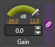
Level controlsLevel controls, which are generally associated with volume, have a continuous series of states that are represented by a slider. The slider typically represents a relative position within a defined range (for example, a percentage value between a configurable minimum and maximum gain value). Several HAL processing blocks contain level controls that you can include in a level control link. The most commonly used are the Level processing block and the RAD and analog input and output blocks. The Level controls on these blocks are typically connected to DR Level controls (found in the Control palette). Following is an image of a Level control (that has been linked) as well as a Level control example:
Level Control Example: You want to provide users with remote volume control of a podium microphone at the front of a room. Let's assume you're using a RAD2 for your microphone input and a DR1 for the remote control hardware. Within Halogen, you link the Gain control within the RAD2 block to the Level control within the DR1. You install the DR1 in the appropriate location in the room, and the end user is able to use the DR1 to control the volume of the microphone.
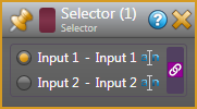
Selector controlsSelector controls do just what the name implies. They allow the end user to select an item from a list. Uses for a Selector control might include selecting a music channel, a preset, a room combination, and so on. You would typically link a Selector control to a DR capable of displaying a list (for example, a DR2 and a DR3).
HAL processing blocks that contain linkable Selector controls are DR blocks (only for DRs that are capable of displaying a list, such as a DR2 and DR3) and Selector blocks (Selector, Selector with Priority, Router).
note: A Selector control allows the user to select only one option in the displayed list. In other words, a Selector behaves like a software radio button.
Following is an image of a Selector control (that has been linked) as well as a Selector control example:
Selector Control Example: Let's say you want to allow end users to select a background music channel from a list of background music channels. You choose a DR2 for your digital remote device. Within the Halogen Hardware Workspace, you add the DR2 to your system and configure it to behave as a Single Selector. You then move to the Processing Workspace (and we'll assume you already have most of your design in place) and link together the Selector control in the DR2 block with the Selector control in the appropriate Selector block in your design. You install the DR2 in the desired location, and, because the DR2 is linked to a Selector block, the DR2's LCD screen displays the Selector block channels. The end user is then able to use the DR2 to select one of the channels.
Toggle controlsToggle controls allow you to switch between two states — on or off. A common usage of a Toggle control is to mute/unmute audio. Another common usage is to activate/deactivate a preset.

note: Toggle controls behave like software checkboxes (unlike Selector controls which behave like radio buttons). In other words, if multiple Toggle items are displayed on the remote device, the user can select or deselect one or more of them.
Toggle Control Example: You want to give your end users the ability to mute or unmute the audio in a specific room. You choose a DR2 for this purpose and configure it (in the Halogen Hardware Workspace) to represent a List of Toggles/Commands. In the Halogen Processing Workspace, you link together the DR2's Toggle control with the appropriate Mute Toggle control in your audio design. The end user can then use this DR2 to mute and unmute the audio to which it is linked.
Command controlsA Command control has no state. It simply allows you to initiate an action. Unlike a Toggle, you cannot undo a Command. The most common usage of Command controls is to assert a preset.
Command Control Example: Suppose you have configured several presets containing different audio configurations for the same room. You want to give the end user the ability to assert the appropriate preset depending on the current audio needs of the room. A list of Command controls works well in this situation. You choose a DR2 for the hardware control and, in the Halogen Hardware Workspace, configure the DR2 to represent a List of Toggles/Commands. You then select Command as the control type (from the dropdown list) and configure the display names for the items in the list — in this case, the different presets. In the Halogen Processing Workspace, you link each DR2 Command control to the Command control of the relevant preset. When the end user selects the preset on the DR2 and pushes the DR2 knob, the selected preset is asserted.
All control links (with the exception of Command Links) include the following components:
- Participants

- Control Link Activation State
- Link Master‡ (
- The Control Link itself
- Control Link Priority (
‡A Command Link has no value to maintain, therefore it does not contain a Link Master or a Control Link Value.
You can choose whether or not to turn a control link on. In other words, you can configure a control link's state by activating or deactivating the link. When you activate the link, the linked controls track one another. When you deactivate the link the linked controls do not track one another.
Let's say you plan to use a DR1 in the lobby of a restaurant to control the volume of the music playing in the dining room. Sometimes the music plays in the lobby as well and, in those instances, you want the DR1 to control the volume in both the dining room and the lobby. You might create two control links for this DR1, with one linking the DR1 level control with the level control for the dining room only, and the other linking the DR1 level control with both the dining room and lobby level controls. You would then activate the control link you want at a given time.
So how do you activate a link? When you create a control link, you configure its state by selecting or deselecting its Active checkbox. For details on the actual procedure, see Activating/Deactivating a Control Link.
That's all fine and good, you say. But how do I then change that state at a later time? Surely I don't have to go into the software every time I want to activate or deactivate a control link! Of course not. This is where presets come in. See the next question (and answer) for details.
You've created a control link and now you want to activate it in certain situations and deactivate it in other situations. You could, of course go into the software and manually select or deselect the Active checkbox any time you want to change the state of a control link. But this would be a bit cumbersome, don't you think? In most cases, you will use presets to alter a control link's state.
note: A preset can change the state of a control link. But a preset cannot change the participants in a control link.
Let's look at the example from the previous question to help illustrate this point. You have a single DR1 that you want to control volume in the restaurant dining room only at certain times, but other times control volume in both the dining room and lobby. You would need to create two control links, as follows:
- Dining Room Only control link has two participants—the DR1 level control and the Dining Room level control
- Dining Room/Lobby control link has three participants—the DR1 level control, the Dining Room level control, and the Lobby level control
The Dining Room only preset would activate the Dining Room only control link and deactivate the Dining Room/Lobby control link. The Dining Room/Lobby preset would do the opposite—activate the Dining Room/Lobby control link and deactivate the Dining Room control link.
You may be tempted to try creating a single control link for the DR1/Dining Room volume control and then using a preset to add or remove the Lobby level control when needed. But this is not possible. Presets can alter only the state of a control link. Presets cannot alter the control link participant list.
best practice: Before creating a control link, you should add all the control participants to the Halogen Hardware Map and Processing Map. In other words, you cannot create a link between two controls until you've made those controls available. For example, if you plan to create a link that includes a DR2 Selector control, you should first add the DR2 to your Hardware Map and configure it to behave as a Selector.
When linking only two controls, the simplest method for creating the link is to drag the link icon from one of the controls and drop it onto the link icon of the other control. If linking more than two controls, there are other issues to consider (see Advanced Topics
The originating control is known as the source and the other control is the target: 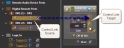
When you drop the link icon from the first control onto the link icon of the second control, a dialog box appears containing up to three possible actions:
- If the two controls are not participants in any other control links, the dialog box contains one option: Create New Link:

- If the source control is a participant in any other control links, the dialog box contains an additional option: Remove From Link:

- If the target control is a participant in any other control links, the dialog box contains an additional option: Add To Link:

In other words, if your intention is to move the source control from one link to another, you can do so by selecting both Remove From Link and Create New Link, or you can simply create the new link, leaving the existing link intact.
In other words, you can select Add To Link to add the source control to a link in which the target control already participates. You can select Create New Link to create a brand new control link between the source and target. Or you can do both.
See Creating a Control Link for more details.
Yes. Click the purple link icon associated with the control. If the control is a participant in only one link, that link's properties dialog box displays. If the control is a participant in multiple links, the control's Link References dialog box opens, displaying all the links in which the control is participating:  The link in which the control is currently active is also noted with a purple link icon.
note: The links in the Links References dialog box are sorted in priority order.
No! A tremendous benefit of HAL System control linking is the ability to test a link as soon as you create it. No hardware is needed. See Testing a Control Link for details.
Yes, you can enable and disable individual DR devices. And you can use control linking to accomplish this! Every control on a DR has an Enable checkbox property, as shown below:

Notice that the Enable checkbox control is also linkable. We know this because of the link icon that appears next to the checkbox label. This checkbox is a Toggle control. It can have two states: Enabled (checkbox is selected) and Disabled (checkbox is deselected). You could also have a preset that enables or disables a specific DR control.
Yes, you can connect switches to your HAL's Logic In ports and then include these controls in a control link. And yes, there are some differences in behavior when including a Logic In control in a control link. Halogen can read the state of a switch connected to a Logic In port but cannot change the switch's state.
Halogen, however, allows you to configure a Logic In toggle in one of two ways: Momentary or Latching. Momentary is intended for use with momentary physical switches (surprisingly enough) and when configured this way, the Logic In port looks for the switch to change from open (not pressed) to closed (pressed) - which is the same as the transition from logic high to logic low. Each time the Logic In port senses this transition, it changes the state of the toggle control associated with the port, as seen in the Control palette in the Processing Workspace. When configured as Momentary, the toggle control is not considered to be a read-only control because the toggle state doesn't correspond to the state of the Logic In port (logic high or logic low). Included a Logic In toggle configured as momentary does not place any special restrictions on the link as it does when you configure the port as latching, as we shall see below.
tip: Since a Logic In toggle configured as momentary is not considered to be a read-only control, other controls that participate in a link with the Logic In toggle are able to change the state of the toggle. This means that you can use DRs or external control system toggles to control a Logic In toggle, which is handy in some situations, such as controlling the wall toggles in a Room Combine application. For example, if you have a physical panel with momentary switches and want to use it and also an external control system to control the wall toggle in a Room Combine block.
When you configure a Logic In toggle as Latching, the associated toggle control in the Control palette of the Processing Workspace follows the state of the connected switch. When the switch is open, the toggle is unchecked while when the switch is closed, the toggle is checked. In this configuration, Halogen considers the toggle to be a read-only control—a characteristic that has ramifications for the control links in which it participates:
- When a link containing a read-only control is active, only the read-only control is enabled in the Halogen software. For example, if you link a two-position switch (connected via a Logic In port) to a Mute control in your Halogen Processing Map, you will no longer be able to toggle the Mute checkbox. It will be disabled in the software. Why is this? Because Halogen cannot send information to a read-only control, it has no way of keeping the controls in sync should one of the other controls in the link be changed within the software. When a read-only control participates in a link, only that control can be changed.
- You cannot include more than one read-only remote device in a single control link. Why? Because read-only devices cannot track one another.
- A read-only control link participant must be the control link's Link Master. In other words, because no other participants in the link can update the read-only control, the read-only control must be the participant in charge of updating the other participants. See below for details on the role of the Link Master.
-
You can configure each HAL Logic In port as a two position selector, allowing you to link the switch connected to the Logic In port to other two position selectors in your system. It is important to note that, in addition to being a read-only control, the Logic In selector can only have two selections. Therefore, once linked, you will no longer be able to increase the number of selections in other participants. For example, once a Logic In selector is linked with a two channel source selector, it is not possible to add channels to the Selector Block.
Advanced Topics
When including three or more controls in a single control link, the direction in which you drag and drop new participants is important, as outlined below:
- If using the All Links dialog box to create the control link, simply drag and drop the new participant onto the link in the All Links dialog box.
OR
- If using the control-to-control drag and drop method, when adding the third or greater control, always drop the new control onto a control already participating in the link. In other words, the control link target should be an existing participant. You can think of the control link like a party. If a person decides to join the party, the person goes to the party, the party doesn't come to the person! If you were to drop one of the link's existing participants onto a new control, Halogen would offer only two options: removing the source control from its existing links, and/or creating a new control link between the source and the target. If, however, you dropped the new participant onto the existing participant, Halogen would offer the option of adding the new participant to the existing control link.
tip: When creating a link that contains more than two controls, think of one control as the bucket into which you'll drop all the other controls. Of course, in keeping with the previous analogy of people coming to a party, you can think of this one control as the party host!
There is no restriction on the number of control links in which a control can participate. However, the control cannot be active in more than one link at a time. For example, a single DR1 Level control could participate in two different control links (Link1 and Link2). But if both Link1 and Link2 are active, the DR1 Level control can be active in only one of the links. How does HAL decide which link governs the DR1 Level control in this situation? The answer? The control link priority.
Halogen places each created control link in a prioritized list. If a control participates in multiple active control links, that control is active only in the control link with the highest priority. Staying with the above example, let's say that Link1 is higher in the priority list than Link2. Link2 is currently active, but then someone activates Link1. What happens to that DR1 Level control? It becomes active in Link1 and is no longer active in Link2.
Even though Priority is set at the link level, it actually governs the individual participants in a link, not the entire link. In the example we just discussed, let's assume there are several other controls participating in Link2 — but not participating in Link1. These other controls remain active in Link2 when Link1 is activated. The following diagram helps illustrate this concept:
(Mouse over the diagram to view it.)

So how do you set the priority for all your control links? As previously mentioned, Halogen automatically places a new control link at the top of the priority list. This list is visible in the All Links dialog box. To adjust the priority, you simply move control links up and down in the list.
note: There is a separate prioritized list for each type of control link.
Every control link contains a Link Master, which is the control link participant that dictates the values of the other link participants at the moment the control link is activated. Depending on the complexity of your system, it's possible you'll never need to think about or concern yourself with a Link Master. In certain situations, however, it's important that you understand its role and why the Link Master is important. For example, if you plan to be deactivating and re-activating control links, you definitely need to understand the Link Master!
To fully explain the Link Master function, let’s begin with a scenario. Suppose that you have two Level controls in your system (LevelA and LevelB). In most situations, these two Level controls work independently, but in a few cases they must track one another. Therefore, you create a control link (Link1) that links LevelA and LevelB. Link1 remains inactive most of the time. While inactive, LevelA and LevelB operate independently and are, therefore, typically set to a different value. So what happens when you activate Link1? Should LevelA snap to LevelB’s value or should LevelB snap to LevelA’s value? This is where the Link Master comes into play. In any control link, one participant is designated as the Link Master. You can accept the default designation or configure it yourself. In this scenario, if LevelA is the Link Master, LevelB and the control link value take on the value of LevelA. If LevelB is the Link Master, Level A and the control link value take on the value of LevelB. As long as Link1 remains active, LevelA and LevelB track the control link value. The following images help illustrate this example:
Inactive Link: 
After activating the link: 
What happens if LevelB participates in another control link (Link2) which is higher priority than Link1? If Link2 is activated, its control link value and all its participants take on the value of the Link2 Link Master (which could be LevelB). LevelB will not be an active participant in Link1 until Link2 is deactivated. When Link2 is deactivated, assuming Link1 is still active, LevelB will become an active participant in Link1. As LevelB rejoins Link1, it takes on Link1’s control link value, even if it is Link Master in Link1. The Link Master is only used to initialize the value of a link when the link is activated. From that point forward (until the link is deactivated), all participants track the control link value.
The following images from the Halogen software help illustrate the above scenario. The first image shows the different controls when both Link1 and Link 2 area active. The second image shows what happens when Link 2 is deactivated.
Both Link 1 and Link 2 are active:
Link 1 is active, Link 2 is inactive: 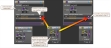
At this point, you may be wondering several things:
Halogen automatically selects the Link Master when you initially create the control link.
- If you are creating your control link by dropping one control onto another, your initial control link target becomes the Link Master. For example, if you dropped a DR1 Level control onto the Gain parameter in a Level block, the Level block becomes the Link Master as it is the target.
- If you are creating your control link by dropping controls into a control link in the All Links dialog box, the first control dropped on the control link becomes the Link Master.
- If you include a read-only control in your control link, the read-only control always becomes the Link Master and disables your ability to change its designation as the Link Master. This is done because the HAL System cannot alter a read-only device.
- Dynamic selectors (selectors that automatically change their number of selections to match the link in which they are participating) cannot be Link Master because they have no value when they are not linked. Therefore, a newly-activated link cannot use a dynamic selector’s value for initialization.
It is recommended that the audio value in your Processing Map be the Link Master—as opposed to your hardware controls. To ensure that this occurs, consider always dragging hardware controls from the palette onto the Processing Map instead of moving from the Processing Map to the palette. Think in terms of what it is that you want to control.
Yes, you can select which participant you want to be the Link Master. To change the Link Master designation for a control link, you access the control link's properties dialog box and select the Link Master you want by selecting the relevant participant's Master radio button: 
There are a few situations, however, in which your choices for Link Master are limited or are made for you:
- If one of the participants is a read-only control, the read-only control is always the Link Master because its value cannot be changed by software. In this situation, the ability to change the Link Master is disabled.
- Dynamic selectors (such as the Selector on DR2s and DR3s) cannot be Link Master because they have no value when they are not active in a control link. The ability to configure dynamic selectors as the Link Master is disabled.
In summary, there are three ways in which a control link's Link Master designation is created:
- You create the control link.
- You manually change the Link Master designation for the control link.
- You add a read-only control to the control link.
note: Because Command control links do not maintain a state or hold a value, these control links do not need a Link Master.
Best Practices
best practice: Always drop any new control link participant onto a control already participating in the link. In other words, the control link target should always be an existing participant. Think in terms of what it is that you want to control.
best practice: Name your links as you create them to help with identification later. For example, if you want to see the links in which a control is participating, the list of links will only make sense if each one is aptly named.
best practice: A handy way to view the links in which a control is a participant is the Link References dialog box. From this dialog box, you can also access details about each displayed link. To access a control's Link References dialog box, simply click the control's link icon. Note that if the control is a participant in only one link, there is no Link References dialog box, but only the single Link dialog box.
best practice: Always test your link after creating it by changing one of the controls and checking if the other control(s) tracks the change.
best practice: If you need a Selector control, use a DR as your remote hardware. DRs are preferable to Logic In selectors as DRs are dynamic, can have more than two selections, include automatic naming of the selections, provide end users with a nice user interface, and fit into a gang box with no custom fabrication.
best practice: To activate and deactivate control links, you must use presets.
best practice: If you want the DR selection names to match the channel names on the linked processing block, create the block's channel name(s) before linking it to the DR.
best practice: In most situations, it is best to drag your hardware controls onto the Processing Map—instead of dragging controls from the Processing Map onto the Control palette. If configured in this manner, your Processing Map audio control will be the Link Master (unless you include a read-only hardware device).