Following are the types of DRs currently available for your HAL System. The DR models available will vary over time as Rane's engineers ponder and design new and better ways to remotely control an audio system. For the most current list of DRs, see the Rane website.
note: Several of the DRs mount inside a US one-gang or two-gang switchbox (DR1, DR2, DR3, and DR5). See the Rane website for a detailed listing of acceptable models of switchboxes. Note that the Decora plates are also included with the DR1, DR2, and DR3.
note for drag net users: Remember the SR3 remote for Drag Net systems and how it was too wide to allow the mounting of two or more of them beside each other in a standard switch box? You will be happy to know that the HAL System DRs can be mounted directly beside each other in any combination, allowing you to use several DRs in the same two, three, or four-gang switchbox.
note: DR1, DR2, and DR3 display screens are dynamic, automatically updating when the available options change through preset activation, room combining, and so on. Therefore, the user always sees the options that are currently available.
A DR1 provides a single level control. A DR1 is used most commonly to control volume.

note: A DR1 requires a one-gang standard switchbox for installation into a wall.
A DR2 works well for selecting sources, presets, and room configurations. You can configure a DR2 to behave in one of two ways:
- Single Selector: The control acts as a selector switch that can select only one item on the display screen. For example, the display screen might show a list of background music channels. The user uses the push control to select which channel to activate. This behavior is similar to a radio button in a software application (as displayed in the image below).
- List of Toggles/Commands: The control acts as a switch for enabling or disabling each item on the display screen. For example, the display screen might list presets and the user uses the push control to enable or disable each preset in the list. This behavior is similar to a series of checkbox items in a software application.

note: A DR2 requires a two-gang standard switchbox for installation into a wall.
The DR3 is extremely flexible, as it can control both selection and volume. You can think of the DR3 as two different remotes—a selector and a level. One knob makes a selection, the other knob changes the volume.
You can configure a DR3 in one of three ways:
- Single Level & Selector: Control a level and selection from the same remote. For example, you could use a DR3 to select the background music source and control the volume in a room.
- Single Level & List of Toggles/Commands: This option allows you to control a single level and multiple other items. For example, you could use a DR3 to control the volume in a room as well as activate/deactivate one or more listed presets that change the audio and control parameters for the room.
- List of Levels: Choose from multiple levels. For example, you could use a DR3 to control the volume in multiple rooms or zones from a single DR located at a hostess station or in a manager's office.

note: A DR3 requires a two-gang standard switchbox for installation into a wall.
The DR4 provides a variety of inputs and outputs: 8 Logic Inputs, 8 Logic Outputs, 8 Analog Control Inputs, and 6 IR Remote Inputs.
These inputs on the DR4 are similar to the Logic In ports on a HAL. You can configure each of the eight input ports in one of three ways:
- Toggle:
The Toggle configuration allows you to control the state of a toggle control in the Control palette of the Processing Workspace. You can configure each port type to be either Momentary or Latching, which tells HAL how to process the port’s input signal. For a complete description of Momentary and Latching toggle inputs, see Momentary and Latching Toggle Configuration.
- Command:
This option allows the Logic In port to trigger a Command control in the Control palette of the Processing Workspace, which you can link to one or more Command controls such as a Command preset or a linkable button in a processing block property dialog.
When nothing is connected to a Logic In port, the hardware internally pulls the port to logic high (5 V). To trigger the command, a hardware device connected to the Logic In port must pull the port voltage lower than the logic low threshold, which is specified in the Rane data sheet for the DR4. One way to do this is to connect a physical normally open momentary push button switch to the port. When the end user pushes the button, the switch contacts close, pulling the Logic In port low, which causes the Command to trigger. When the user releases the button, the port signal returns high and the port is ready for the next command.
The following diagram shows a momentary switch wired to a DR4 Logic In port.

- Selector:
In this option, you can configure one or more Logic In ports to control the state of a corresponding selector control in the Control palette of the Processing Workspace. You can connect a physical device to any or all of the Logic In ports and configure the ports in Halogen so that they make the desired selection according to the state of the physical device.
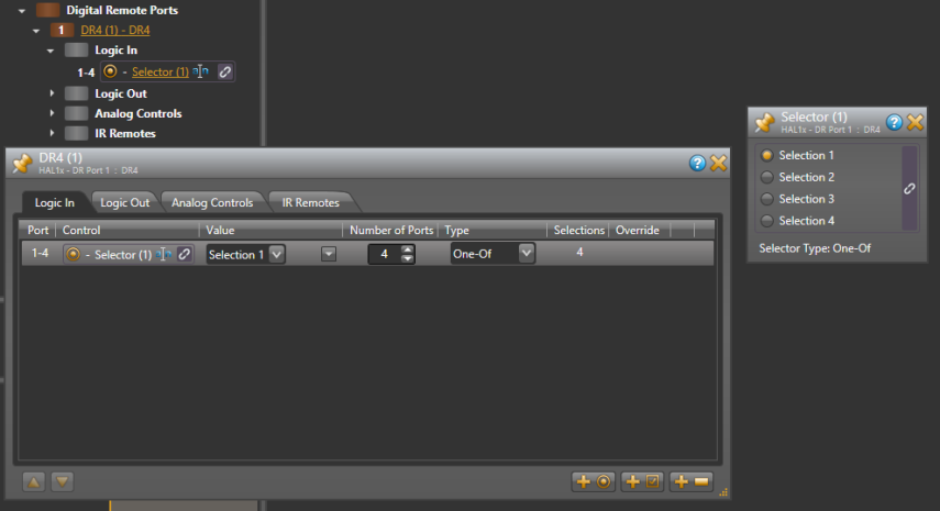
One-Of Selector
One type of physical device is a multi-position switch, which can connect one common contact to any one of a set of other contacts. For example, suppose you have a four position switch, which has four contacts and a common. When the switch is in position one, the switch connects contact number one with common, leaving the other three contacts open. When the user changes the switch to position two, it disconnects contact one and connects contact two to common, and so on.
In Halogen, we refer to this type of physical switch as a ‘One-Of’ selector. It connects one (and only one) of the contacts in a set to a common pin on the switch. To use this type of switch with the DR4 Logic In ports, configure the Logic In ports to be a selector (Select in the drop down box) with the desired number of ports (four in our example) and set the type to be One-Of. When the connection to a Logic In port is open (not connected to ground), the hardware pulls the input to a logic high value (5 V). When a connected device pulls the port below the logic low threshold (specified in the DR4 data sheet), the port senses this and, when configured as part of a one-of selector, sets the value of the corresponding selector control in the Processing Workspace.
The default value of a one-of Selector control is to select the first item in the list of selections.
The example below shows how a DR4 one-of selector works. The following diagram shows how to wire a multi-position switch to a set of DR4 ports.

The image below shows the corresponding Selector control in the Control palette of the Processing Workspace. It also includes the DR4 property dialog showing the Logic In port configuration:
The following table shows how changing the physical switch position affects the Logic In ports and the corresponding Selector control:
Switch Position Logic In Port Selector Control 4 3 2 1 1 High High High Low Selection 1 2 High High Low High Selection 2 3 High Low High High Selection 3 4 Low High High High Selection 4 A set of DR4 Logic In ports configured as a one-of selector is not a read-only control because the ports only sense when the switch closures occur – that is when the port input signal goes from logic high to logic low as described above. This means that you can link the corresponding selector control in the Processing Workspace to other selector controls and each of the participants can change the selection value. It also means that this approach works best with a physical selector that uses a set of momentary normally open push button switches.
While the port is not read-only, other selectors can change and follow each other, but the physical switch cannot follow – thus the switch may not always show the proper indication. All selectors return to the physical switch setting the next time the physical switch is changed.
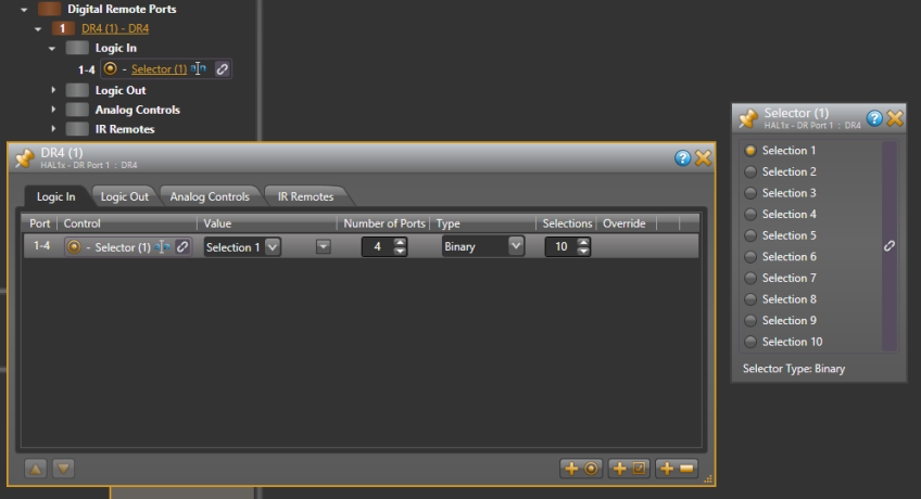
Binary Selector
The other type of physical selector device that you can use with a DR4 Logic In is called a ‘Binary Selector’. This type of device converts a physical control setting to a binary output value. For example, you might have a switch that has a number of selections, say from 1 to 10. This switch has five pins total – four contacts and a common. When the user changes the switch setting, the switch connects the appropriate contact pins to common such that they represent the binary value of the selected setting.
In Halogen we refer to this type of device as a ‘binary’ selector. It connects zero or more of the contacts to common to represent a binary number that is the desired selection. To use this type of switch with the DR4 Logic In ports, configure the Logic In ports to be a selector (Select in the drop down box) with the desired number of ports (four in our example) and set the type to be Binary. Set Selections to be the maximum number of different binary numbers that your switch can represent (10, in our example above). As the user changes the switch setting, the DR4 ports sense the binary value that the switch represents and sets the selection of the corresponding selector control in the Processing Workspace.
Of course we need an example. The following diagram shows how to wire a 10 position binary switch to a set of DR4 Logic In ports:
The image below shows the corresponding Selector control in the Control palette of the Processing Workspace. It also includes the DR4 property dialog showing the Logic In port configuration:
The following table shows how changing the physical switch position affects the Logic In ports and the corresponding Selector control:
Switch Position Logic In Port Selector Control 4 3 2 1 1 High High High High Selection 1 2 High High High Low Selection 2 3 High High Low High Selection 3 4 High High Low Low Selection 4 5 High Low High High Selection 5 6 High Low High Low Selection 6 7 High Low Low High Selection 7 8 High Low Low Low Selection 8 9 Low High High High Selection 9 10 Low High High Low Selection 10 A set of Logic In ports configured as a binary selector is read-only. This is because the physical switch sets the signal level of each DR4 port that it is connected to and these signals are constant for as long as the switch is in one position.
You can configure each of the eight output ports in one of two ways:
- Toggle: The Toggle configuration allows the state of a toggle control in the Control palette of the Processing Workspace to control the state of the Logic Out port. When the toggle control is unchecked, HAL sets the corresponding DR4 Logic Out port to logic high (5 V) and when the toggle is checked, it sets the port to logic low (0 V). See the DR4 data sheet for more details on electrical specifications for the DR4 Logic Out ports.
- Selector: The Selector configuration allows the state of a two position selector control in the Control palette of the Processing Workspace to control the state of the Logic Out port. When the selector control is set to the first selection, HAL sets the corresponding DR4 Logic Out port to logic high (5 V). Conversely, when the selector control is in the second position, HAL sets the port to logic low (0 v). See the DR4 data sheet for more details on electrical specifications for the DR4 Logic Out ports.
Each port allows an analog voltage source to control the value of a Level control in the Control palette of the Processing Workspace. The input range for the port is from 0 V to 5 V, where 0 V corresponds to 0% on the associated Level control and 5 V corresponds to 100%. The DR4 Analog Control input is protected from voltage outside of that range up to certain limits, see the DR4 data sheet for details. Applied voltages outside of the 0-5 V range, however, will limit the corresponding Level control to maximum or minimum, depending on whether the applied voltage is under or over the allowed limit. For example, if you apply 6 V to the port, the corresponding level control will be set to 100%, because it is over the allowed 5 V limit.
One way to use a DR4 Analog Control Input port is to connect a physical potentiometer as shown in the diagram below, which shows the Rane VR2 Volume Remote connected to a DR4. By wiring it this way, the Vc wiper provides the control voltage to the DR4. As you adjust the VR2’s knob, the voltage changes on the control pin of the DR4 port, which in turn changes the corresponding Level control in the Control palette of the Processing Workspace.
The following diagrams shows how to wire a VR2 to a DR4 Analog Control Input:
The image below shows the corresponding Level control in the Control palette of the Processing Workspace and how to link it to a Level control in a HAL Line Output block. It also includes the DR4 property dialog, showing the Analog Controls tab:
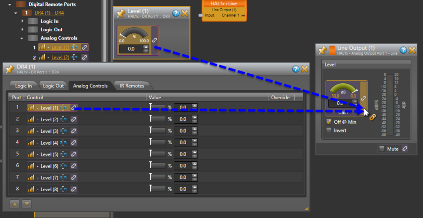
note: The above image shows how you can link a level control using either the Level Control dialog or the DR4 property dialog. Just click and drag the link icon to the link icon of the control you wish to link to.
You should use only linear "B" taper potentiometers with the DR4 Analog Control inputs because the corresponding Level control is ratio-metric (that is ranges from 0 – 100% in a linear manner). The HAL system applies any necessary taper to level controls that participate in a link. For example all Level controls that affect audio gain in the HAL system have an audio taper applied.
The Level controls in the Processing Workspace that correspond to each DR4 Analog Control input are read-only controls. This is because the physical hardware connected to the DR4 port (for example a potentiometer) determines the ratio-metric value of the Level control. The analog input signal is constant as long as the device is attached and remains in the same position.
The IR ports provide six toggle inputs to the HAL system and are ideal for linking to the wall toggle controls in a Room Combine block. This allows automatic room configuration changes to occur as moveable walls change positions in the physical room. These ports are read-only and are not configurable, but are intended for use with a Rane IR2 device. When the IR Remote is sensing infrared the wall is considered 'open' and the associated toggle control in the Control palette of the Processing Workspace is checked.
Following are pictures of the rear and front panels of a DR4.


note: A DR4 is a 1U rack mounted device that requires a standard AC IEC power connection.
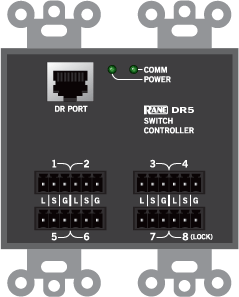
The DR5 Switch Controller Remote provides eight Switch Input/LED Output pairs intended for use with a custom built lighted room combine switch panel.
Switch Inputs
These inputs on the DR5 are similar to the Logic In ports on a HAL. You can configure each of the eight input ports in one of two ways:
- Toggle:
The Toggle configuration allows you to control the state of a toggle control in the Control palette of the Processing Workspace. You can configure each port type to be either Momentary or Latching, which tells HAL how to process the port’s input signal. For a complete description of Momentary and Latching toggle inputs, see Momentary and Latching Toggle Configuration.
- Command:
This option allows the Switch Input port to trigger a Command control in the Control palette of the Processing Workspace, which you can link to one or more Command controls such as a Command preset or a linkable button in a processing block property dialog.
When nothing is connected to a Switch Input port, the hardware internally pulls the port to logic high (5 V). To trigger the command, a hardware device connected to the Switch Input port must pull the port voltage lower than the logic low threshold, which is specified in the data sheet for the DR5. One way to do this is to connect a physical normally open momentary push button switch to the port. When the end user pushes the button, the switch contacts close, pulling the Switch Input port low, which causes the Command to trigger. When the user releases the button, the port signal returns high and the port is ready for the next command.
In addition, you can configure port 8 to serve as a 'lock' input, allowing the user to selectively enable or disable all seven input ports with a physical switch attached between Switch Input port 8 and ground (G). When configured as a lock, the DR5 disables Switch Input ports 1 - 7 when the switch is closed and enables the ports when the switch open.
note: To use the lock port, you must configure Switch Input 8 as a Toggle type of input. Once you have enabled the 'lock' port, you cannot move Switch Input port 8 or change it's type to Command.
LED Outputs
The DR5 provides eight LED output ports that are coupled to the state of the corresponding DR5 switch input controls. You can connect an LED to each port to have a visual indicator of the DR5 operations. The operation of an LED Output port is governed by the Switch Input port configuration as follows:
- Toggle: If the corresponding Switch Input port is configured as a toggle, the LED Output port follows the state of the Toggle control in the Control palette of the Processing Workspace. When the Toggle control is checked, the LED Output is high, turning the connected LED on. When the Toggle control is unchecked, the connected LED is off.
- Command: When the corresponding Switch Input port is configured as a Command, the LED Output port follows the state of the Switch Input signal. When the switch is closed, the LED Output is high, turning the connected LED on. When the switch is open the connected LED is off.
The following is a picture of the DR5 panel.
The following is a wiring diagram for the DR5 panel.

note: A DR5 is designed to fit in a standard US two-gang electrical box. Alternatively, you can mount it near a room combine switch panel.
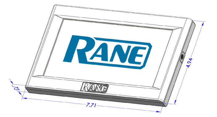
The DR6 is a fully customizable touch-screen remote for the HAL system. It supports multiple pages or tabs and any set of levels, toggles, selectors and/or commands. Using the Control Page Designer, you can drag, drop and resize controls any way that’s desired. You can also use custom background images and logos in full-color on the 7-inch LCD display.
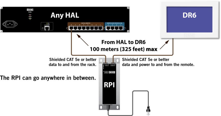
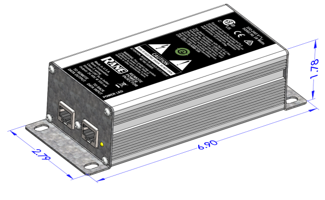
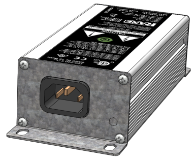
The DR6 uses a Remote Power Injector (RPI) that connects between a DR port and the DR6 device. The RPI provides power for the DR6 and has a dedicated port for the connection to the DR port on a HAL or EXP and another for the connection to the DR6 device:
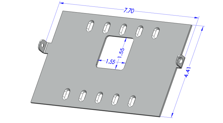
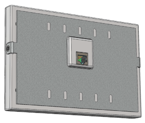
The DR6 includes a wall plate that lets you mount the device in a variety of ways:
The assembled rear view showing the CAT 5e cable connection to the RPI:
 See Also