Digital Remote Control Properties
- Click the Processing tab to open the Processing Workspace.
- On the Processing Palette, click the Control tab.
- Find the Digital Remote device under a Digital Remote Ports category (or Remote Audio Device Ports category as DRs can connect to those ports as well) in the palette.
- Click the arrow next to a device name to expand the list and show the individual DR controls.
- Click the control name, which is a hyperlink, to open its properties.

note: DRs are not available on the Control tab until you have added them from within the Hardware Workspace.
Provides a central location for:
- customizing the text displayed on the DR
- linking the DR control(s) with one or more other processing control(s) in the system
- changing the Level value (Level control only)
- changing which item is selected (Selector control only)
- changing the Toggle state (Toggle control only)
- asserting the Command (Command control only)
- enabling or disabling the control
Some Digital Remote controls are read-only and behave slightly differently if connected to a HAL versus not connected to a HAL. When connected, read-only controls are enabled in the software but usually follow the state of hardware (e.g. switches) attached to the DR port. You can override the physical state of a read-only control in the properties dialog so that you can test the link. Do this by simply changing the control in the dialog to the state that you want to test.
When connected, Halogen indicates an overridden condition by showing a  button in the control dialog and by displaying a global Cancel Port Overrides dialog which allows you to cancel overrides for all controls, reverting to the actual state of the Logic In ports.
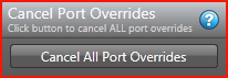
When not connected, Halogen does not display the Cancel Override button or the Cancel Port Overrides dialog.
note: HAL cancels all read-only overrides when you disconnect Halogen or on HAL reboot.


| UI Element | Purpose |
|---|---|
| Display Label | Shows the label that will appear on the DR device. You can type a custom label in the edit box. |
| Level Value | Reflects the value (from 0 to 100%) of the Level control, which you can manually adjust from within the software. The control does not alter audio level, however, until you link it to a Level control on the Processing Map by clicking, dragging, and then dropping the DR Level link icon onto the link icon of the Level control on the Processing Map. When the two controls are linked, they track one another (as long as the link is active). |
| Enabled |
Designates whether or not this DR Level control is enabled. You can manually enable or disable the control from within the software, or provide end users with the ability to enable or disable the control—by saving the desired state to a preset that is exposed to end users, or by linking the Enable Toggle control to another DR Toggle control. note: When a control is disabled, it does not appear on the display of the Digital Remote device. The control is still functional in Halogen, but the user cannot use the control on the physical DR. You can use this setting to selectively change which controls the user is able to view and use on each DR depending on your application. |
|
Cancel Override (online only) |
Appears when you have overridden the current state of the physical analog control attached to an Analog Control Input or Logic In port. Click the button to revert to the actual state of the Analog Control Input or Logic In port. note: HAL cancels all read-only overrides when you disconnect Halogen or on HAL reboot. |


| UI Element | Purpose |
|---|---|
| Display Label | Shows the label that will appear next to this Toggle choice on the DR device. You can type a custom label in the edit box. |
| Toggle | Reflects the current state of the Toggle control—on (checkbox is selected) or off (checkbox is not selected), which you can control from within the software. The control does not alter audio level, however, until you link it to a Toggle control on the Processing Map (for example, a Mute or Preset Active control). To do so, click, drag, and drop the DR Toggle link icon onto the link icon of the Toggle control on the Processing Map. When the two controls are linked, they track one another (as long as the link is active). |
| Enabled |
Designates whether or not this DR Toggle control is enabled. You can manually enable or disable the control from within the software, or provide end users with the ability to enable or disable the control—by saving the desired state to a preset that is exposed to end users, or by linking the Enable Toggle control to another DR Toggle control. note: When a control is disabled, it does not appear on the display of the Digital Remote device. The control is still functional in Halogen, but the user cannot use the control on the physical DR. You can use this setting to selectively change which controls the user is able to view and use on each DR depending on your application. |
|
Toggle Type |
Shows the configuration of the toggle in the Hardware Workspace: Latching or Momentary. Latching toggles are read-only while Momentary are not. |
| Cancel Override (online only) |
Appears when you have overridden the current state of the physical switch attached to a Logic In port. Click the button to revert to the actual state of the Logic In port. note: HAL cancels all read-only overrides when you disconnect Halogen or on HAL reboot. |


| UI Element | Purpose |
|---|---|
| Display Label | Shows the label that will appear above the selection list on the DR device. You can type a custom label in the edit box. |
| Selections |
Displays the list of selections available to end users on the DR. This list is not populated until the Selector control is linked to a Selector control on the Processing Map. To do so, click, drag, and drop the DR Selector link icon onto the link icon of the Selector control on the Processing Map. When the two controls are linked, they track one another (as long as the link is active). Provide custom names for each selection by typing in the edit box provided. This name is visible on the actual DR device. When a Logic In selector participates in a link, you can provide custom names for each selection by clicking the edit icon and then typing in the edit box that appears. This name is part of the link and is visible on the DR displays that participate in the active link. |
| Enabled |
Designates whether or not this DR Selector control is enabled. You can manually enable or disable the control from within the software, or provide end users with the ability to enable or disable the control—by saving the desired state to a preset that is exposed to end users, or by linking the Enable Toggle control to another DR Toggle control. note: When a control is disabled, it does not appear on the display of the Digital Remote device. The control is still functional in Halogen, but the user cannot use the control on the physical DR. You can use this setting to selectively change which controls the user is able to view and use on each DR depending on your application. |
|
Selector Type |
Shows the configuration of the selector in the Hardware Workspace: One-Of or Binary. Binary selectors are read-only while One-Of are not. |
| Cancel Override (online only) |
Appears when you have overridden the current state of the physical selector hardware attached to a Logic In port. Click the button to revert to the actual state of the Logic In port. note: HAL cancels all read-only overrides when you disconnect Halogen or on HAL reboot. |

| UI Element | Purpose |
|---|---|
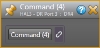
| Display Label | Shows the label that will appear next to this Command button on the DR device. You can type a custom label in the edit box. |
| Command | Click the button to assert the Command. Asserting the Command does little, however, until you link it to a Command control on the Processing Map (for example, a Command preset). To do so, click, drag, and drop the DR Command link icon onto the link icon of the Command control on the Processing Map. When linked, asserting the DR Command then asserts the linked Command. |
| Enabled |
Designates whether or not this DR Command control is enabled. You can manually enable or disable the control from within the software, or provide end users with the ability to enable or disable the control—by saving the desired state to a preset that is exposed to end users, or by linking the Enable Toggle control to another DR Toggle control. note: When a control is disabled, it does not appear on the display of the Digital Remote device. The control is still functional in Halogen, but the user cannot use the control on the physical DR. You can use this setting to selectively change which controls the user is able to view and use on each DR depending on your application. |
 See Also