Gate
Gates control unwanted noise and unwanted signal pickup by closing a microphone or audio channel when the signal level drops below a set threshold. The primary use of Gates in live sound applications is for gating drum microphones and instrument pickups. The most common use for gates in installed sound reinforcement is for gating microphones used for speech reinforcement. Gated auto-mixers represent the most common use. Employing an individual Gate on a single microphone is less common, but not unheard of. Halogen provides advanced gain-sharing auto-mixer blocks that are easier to set up and provide better overall performance than a gated auto-mixer. The Gate block provides a basic tool for system designers to solve problems related to an individual microphone or audio channel.
Like an Expander, the gain reduction in a Gate occurs below the threshold. Like a Limiter, a Gate must respond very quickly to changes in level, requiring the use of an accurate peak detector in the side-chain. Gates differ from Expanders in that they use a fixed amount of gain reduction determined by the depth control. Gates remove background noise by closing the audio channel when the signal level drops below the threshold. Most Gate applications require side-chain equalization on an external side-chain input, so side-chain low-cut and high-cut filters are included in the Gate. The Gate is able to open very quickly without clicking by using look-ahead delay in the main signal path and pre-ramped gain control in the side-chain. The Gate hold function prevents the Gate from closing during brief excursions below the threshold.
Gates must turn on quickly. Accurately capturing and reproducing transient signals requires accurate peak detection. Accordingly, the Gate uses over–sampled peak detection. Look-ahead and pre-ramping techniques ensure fast and artifact-free gating. A look-ahead detector works by delaying the main audio signal a short amount while not delaying the side-chain signal. This allows examining the signal in advance to determine the appropriate response before an event. This action allows the Gate to turn on before the leading edge of the signal. This in turn allows the turn-on to ramp up instead of step on, avoiding the annoying click resulting from deep gate depth, high threshold and fast attack settings. With digital signal processing, it is possible to delay the main signal path as long as desired. The limiting factor is the amount of delay that the application tolerates. A delay of 16 samples (0.33 ms) with a sample rate of 48 kHz, combined with exponential ramping has proven to provide smooth, artifact-free gating.
For additional information on Gate functionality, take a look at the following RaneNotes:
- RaneNote 155: Dynamics Processors -- Technology & Applications (see Chapter 5)
- Click the Processing tab to open the Processing Workspace.
- In the palette area, click the DSP tab.
- Expand the Dynamics category of blocks.
- Click and drag the Gate block into your Processing Map.
- Wire it into your system in the appropriate location.
- (Optional) Customize the names of the block and the input and output node by clicking their current name and then typing the custom name in the text box that appears. Click the X to save the name.
note: When not externally wired, the side-chain automatically connects internally to the main input.
- Open the Gate block's properties by double-clicking the block or hovering and clicking the properties icon that appears in the upper right of the block's title bar. From here, you can set the values for the following parameters:
- Gain Calculation (Threshold and Depth)
- Rate Control (Attack, Release, and Hold Time)
- Side-chain Control (Low-cut filter, High-cut filter)
note: You can find the definitions of these parameters in the next section.
| UI Element | Purpose |
|---|---|
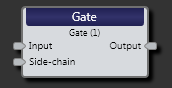
| Input node | Connection point for wiring input to the Gate block |
| Side-chain node |
The Gate’s detector is fed from the side-chain input node. Often the same audio feeding the main input also feeds the side-chain, but advanced users can get fancy and use another signal to achieve audio gating bliss. Included side-chain filters cover most application needs and keep unwanted frequencies from kicking on the gate inadvertently. |
| Output node | Connection point for wiring the Gate input signal to another block |

| UI Element | Purpose |
|---|---|
| Response graph/meter | Graphical representation of signal with Gated indicator. Use the green handles to coarsely adjust Threshold and Depth. A real-time side-chain meter shows the signal relative to Threshold. |
| Threshold |
Represents the side-chain level in dBFS below which the gate is closed (attenuation applied). |
| Depth | Determines how much attenuation in dB to apply to the main input signal when the side-chain level goes below the threshold. |
| Attack | Defines how quickly the Gate responds to a stepped increase in side-chain level. For gates, this defines how quickly the gate opens up (gain turns up) once the side chain level exceeds the Threshold. Because increasing time has a diminishing effect on gain reduction, the attack parameter represents the time it takes for gain to settle to 95% of the final value. |
| Release | Defines how quickly the Gate responds to a stepped decrease in side-chain level. For gates, this defines how quickly the gate closes (gain turns down) once the side chain level drops below the Threshold. The Release parameter represents the time required for a 10 dB change. |
| Hold Time | Defines how long the Gate remains open after the side chain level drops below the threshold. This allows pauses or breaks in the program material without causing the gate to operate. |
| Low-cut Filter | The 2nd-order Butterworth Low-cut filter sets the lower pass-band for the side-chain. This parameter adjusts the frequency in one Hertz steps. |
| High-cut Filter | The 2nd-order Butterworth High-cut filter sets the upper pass-band for the side-chain. This parameter adjusts the frequency in one Hertz steps. |
| Bypass |
Checking the Bypass checkbox turns the Gate block into a straight-through wire, although the side-chain meter continues to function. Yellow bars in the Processing Map indicate a bypass. |
 See Also