Expander
Expanders, which are often used with microphones or any source with noise in the background, increase the dynamic range of a signal by lowering the noise floor.
Expanders complement Compressors by increasing (expanding) the dynamic range of the signal. For example, a compressed input dynamic range of 70 dB might pass through an Expander and exit with a new expanded dynamic range of 110 dB. Unlike a Compressor, the Expander reduces gain for signals below the threshold. The ratio still defines output change verses input change. For example, with a ratio of 2:1, for every 10 dB of reduction in input signal, the output is reduced by 20 dB. Operating in this manner, Expanders make the quiet parts quieter. The term downward expander (or downward expansion) evolved to describe this type of application.
The most common use of an Expander is noise reduction. For example, suppose an expander’s threshold level is set just below the quietest vocal level and the ratio control is set for 2:1. In this scenario, when the vocal stops, the signal level drops down to the noise floor. If the noise floor is 10 dB below the threshold, the expander turns the level down an additional 10 dB (due to the 2:1 ratio, a 10 dB decrease becomes a 20 dB decrease), thus resulting in a noise floor improvement of 10 dB.
tip: The Expander is preferred over the Gate in applications requiring a smoother, more transparent response as the noise level decreases and increases.
- Click the Processing tab to open the Processing Workspace.
- In the palette area, click the DSP tab.
- Expand the Dynamics category of blocks.
- Click and drag the Expander block into your Processing Map.
-
tip: It is best to locate Expanders close to the source, before EQ or other signal processing.
- Wire it into your system in the appropriate location.
- (Optional) Customize the names of the block and the input and output node by clicking their current name and then typing the custom name in the text box that appears. Click the X to save the name.
note: When not externally wired, the side-chain automatically connects internally to the main input.
- Open the Expander block's properties by double-clicking the block or hovering and clicking the properties icon that appears in the upper right of the block's title bar. From here, do the following:
- Set the Side-chain Low-cut and High-cut filters to limit the pass-band to include only those frequencies present in the intended program material. For speech, setting the Low-cut filter at 200 Hz and the High-cut filter at 3 kHz is appropriate.
Set the Threshold to a level equal to the quietest program material. For a microphone at a podium, this is a level equal to the softest expected speech. It is best if final threshold calibration is part of a live calibration test after system installation. This allows the installer to view real microphone levels on the side-chain meter relative to the threshold and accurately set the threshold.
- Set the Ratio for the noise reduction desired. The greater the difference between the Threshold setting and the actual noise floor, the lower the Ratio may be set. For example, if the Threshold is set at -50 dBFS and the actual noise floor, including background noise picked up by the microphone, is -60 dBFS, then a Ratio of 2:1 results in 10 dB of noise reduction. For best performance, use the lowest Ratio setting resulting in the required noise reduction. It is best if final Ratio calibration is part of a live calibration test after system installation. This allows the installer to view the actual gain reduction on the side-chain meter to verify the desired noise reduction.
The Attack time determines how quickly the Expander turns up when speech resumes. In order to prevent loss of content, the Expander must turn up relatively quickly. Typical settings are in the range of 10 to 25 milliseconds. Limiting how far the gain must turn up when speech resumes (by keeping the ratio as low as feasible) is the key reason for using no more noise reduction than required.
note: This configuration does not limit the frequency response of the heard main input signal—only the frequency response of the side-chain. Eliminating frequencies outside those of interest improves Expander performance by preventing unwanted signals from affecting the gain reduction.
The Release time determines how quickly the Expander turns down the Gain. To prevent pumping or excess Gain reduction during pauses in speech, the Release time is set relatively long. Typical settings are in the range of 1 to 5 seconds. With ratios greater than 2:1, the Release time should be in the range of 3 to 5 seconds.
| UI Element | Purpose |
|---|---|
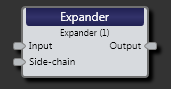
| Input node | Connection point for wiring input to the Expander block |
| Side-chain node |
The Expander’s detector is fed from the side-chain input node. Typically the same audio feeding the main input also feeds the side-chain. This independent side-chain input is supplied for the rare case when the included side-chain filters are not enough. Adjustable side-chain filters aid in keeping unwanted frequencies from meddling with the wanted audio feeding the detector. |
| Output node | Connection point for wiring the Expander input signal to another block |

| UI Element | Purpose |
|---|---|
| Response graph/meter | Graphical representation of signal. Use the green handles to coarsely adjust Threshold and Ratio. A real-time side-chain meter shows the signal relative to Threshold. |
| Threshold |
Represents the side-chain level in dBFS below which signals expand downward. A difference amplifier compares the output of the rms detector (dBFS) to the set threshold (dBFS). The result is a signed dB value relative to the threshold. Values at or above the threshold drive a side-chain dBr meter. Values below the threshold result in gain reduction as determined by the Ratio setting. |
| Ratio | Determines how much attenuation in dB to apply to the main input signal when the side-chain level goes below the threshold. |
| Attack | Determines how fast the expander turns up when the side chain level resumes. Because increasing time has a diminishing effect on gain reduction, the attack parameter represents the time it takes for gain to settle to 95% of the final value. |
| Release | Defines how quickly the Expander responds to a stepped decrease in side-chain level. This defines how quickly the gain turns down. The Release parameter represents the time required for a 10 dB change. |
| Low-cut Filter | The 2nd-order Butterworth Low-cut filter sets the lower pass-band for the side-chain. This parameter adjusts the frequency in one Hertz steps. |
| High-cut Filter | The 2nd-order Butterworth High-cut filter sets the upper pass-band for the side-chain. This parameter adjusts the frequency in one Hertz steps. |
| Bypass |
Checking the Bypass checkbox turns the Expander block into a straight-through wire, although the side-chain meter continues to function. Yellow bars in the Processing Map indicate a bypass. |
 See Also