Mixer
Functionality
The Mixer Block mixes multiple input signals into a single output channel.
How to Use
Use the Mixer Block to mix multiple input signals into a single output channel.
Adding the Block to Your System
- Click the Processing tab to open the Processing Workspace.
- In the palette area, click the DSP tab.
- Expand the Mixers category of blocks.
- Click and drag the Mixer block into your Processing Map.
- Wire it into your system in the appropriate location. If you need additional inputs, simply wire to the <Add> node or click the <Add> text.
- (Optional) Customize the names of the block and/or the input channels and output channel by clicking their current name and then typing the custom name in the text box that appears. Click the X to save the name.
Configuring the Block
- Open the Mixer block's properties by double-clicking the block or hovering and clicking the properties icon that appears in the upper right of the block's title bar. The properties dialog box displays the input channels and output channel, displaying up to four input channels at a time. Use the scroll bar (located beneath the inputs) to bring other inputs into view. Each input channel includes both a Signal presence indicator and a Mute control that can mute the input so that it is silenced in all outputs.
note: These signal indicators are actually meters, therefore they are subject to the same 16 active meter limit as all other meters.
- Enable inputs by ensuring that the channel is unmuted.
- Control the relative volumes of input signals in the output using the level controls in each column. Each input is attenuated by the level of the control in the input column and then they are all summed together before reaching the output level. The output level controls the volume of the entire mix. Once the relative mix of audio signals sounds correct, use the output level control and meter to set the output signal’s rms level to your system’s nominal signal level (typically -20 dBFS). To mute the mix output without changing the output level control, select the output's Mute checkbox.
- Provide end user control over the input mutes, input levels, or output mute or level by linking these controls to corresponding controls on DRs. For example, to provide simple mixer control to the end user, add a DR3 to your system and configure it to behave as a list of levels. Add a DR3 level control to the DR3 for each input to the mixer. Link each DR3 level to an input level on the mixer. Now the end user has full control over the mix.
From this dialog box, you can do the following:
User Interface Elements
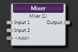
Mixer Block
| UI Element | Purpose |
|---|---|
| Input nodes | Connection points for wiring input to the Mixer block |
| Output node | Connection point for wiring the Mixer input to a specific output |
| <Add> node | Click to add another Output node, or wire to the <Add> not to automatically create a new channel. |
Mixer Block Properties
(Hover over the thumbnail below to view the properties dialog box.)
| UI Element | Purpose |
|---|---|
|
Input Level (Manual and Linkable Control) |
Control the relative volume of an input signal. Each input is attenuated by the level of the control in the input column and then they are all summed together before reaching the output level. Provide end users with control over input volume by linking this Level Control to the Level Control of a DR1 or DR3. |
| Input Mute (Manual and Linkable Control) | Mute this input. Provide end users with mute control by linking this Toggle Control to the Toggle Control of a DR2, DR3, or Logic In. |
| Input Signal | Lights when a signal is detected on this input, turns red if signal overload occurs. |
| Output Level (Manual and Linkable Control) | Control the volume of the entire mix. Provide end users with control over the output volume by linking this Level Control to the Level Control of a DR1 or DR3. |
| Output Mute (Manual and Linkable Control) | Mute the mix output without changing the output level control. Provide end users with output mute control by linking this Toggle Control to the Toggle Control of a DR2, DR3, or Logic In. |
| Output Off @ Min Checkbox | When checked, causes the audio to mute completely when dialed to the low end of its range. |
| Overall Mute Checkbox | Mute output from Mixer block. Manual control only. |
 See Also