Gain-sharing Auto Matrix Mixer
Using the Gain-Sharing Auto Matrix Mixer block, you can create a set of mix-minus microphone mixes. For each output, the Gain-sharing Auto Matrix Mixer block sums all of the inputs, measures the level of that sum, and attenuates all input crosspoints by the difference between their level and the level of the sum. The attenuated crosspoint signals are mixed together and sent to that row’s output level control and meter. This simple algorithm amounts to automatically riding the channel faders on a mixer, turning up microphones in use, and pulling down faders for unused microphones to avoid feedback. The gain-sharing algorithm results in the same 3 dB attenuation per doubling of open microphones that you may be familiar with from working with gated automixers. However, gain-sharing goes further by maintaining a constant level of background noise reinforcement (without requiring the last mic on feature of gated automixers), attenuating two open mics with coherent input signals by 6 dB per mic (avoiding the 3 dB bump that gated mixers give to a talker who is equidistant from two microphones), eliminating gate thresholds that may trip erroneously due to background noise (unintentionally gating on all microphones), and eliminating gate timing (that could clip the first syllable off of a new talker’s speech). In general, gain-sharing mixers are easier to configure and operate than gated automixers, while sounding better too.
The Gain-sharing Auto Matrix Mixer also has a priority level setting. Any crosspoint that has priority enabled lies to the gain-sharing algorithm, saying that it’s X dB hotter than it actually is (where X is the priority level). Effectively, this behavior forces non-priority inputs in that row to duck by the priority level whenever one or more people talk into one or more priority inputs.
Use the Gain-Sharing Auto Matrix Mixer block to create a set of mix-minus microphone mixes.
- Click the Processing tab to open the Processing Workspace.
- In the palette area, click the DSP tab.
- Expand the Mixers category of blocks.
- Click and drag the Gain-sharing Auto Matrix Mixer block into your Processing Map.
- Wire it into your system in the appropriate location. If you need additional inputs or outputs, simply wire to the <Add> node or click the <Add> text.
- (Optional) Customize the names of the block and/or the input and output channels by clicking their current name and then typing the custom name in the text box that appears. Click the X to save the name.
- Open the Gain-sharing Auto Matrix Mixer block's properties by double-clicking the block or hovering and clicking the properties icon that appears in the upper right of the block's title bar. The properties dialog box displays the input and output channels, displaying up to four of each at a time. Use the scroll bars (located beneath the inputs and to the right of the outputs) to bring other inputs/outputs into view. Each input channel includes both a Signal presence indicator and a Mute control that can mute the input so that it is silenced in all outputs.
- Enable inputs by ensuring that the channel is unmuted.
- For each output, decide which inputs you want mixed into that output channel. Enable those inputs by selecting their Enable checkboxes.
- For each output, decide if you want to give any inputs priority. If so, select their Priority checkbox and set the Priority Level to taste.
- Control the mix volume. Each output level controls the volume of the mix for its row. In a mix-minus scenario, use the output levels to set the relative levels between mix-minus reinforcement areas in the room. To mute the mix output without changing the output level control, use its Mute checkbox.
- Provide end user control over input mute, crosspoint priority, or output level by linking those controls to the relative controls on one or more DRs. For example, if the automixer is creating a mix-minus for a court room, link a DR or momentary switch to the judge’s priority checkbox (with a priority level of 6 dB) to give the judge a soft-override button, or link that override button to all the other mixer input mutes to let the judge mute those lawyers. Since the output levels are controlling the relative levels of the mix-minus outputs, consider adding a multi-channel Level block in series with the outputs to control the overall volume. Link a DR1 or DR3 level control to the Level block's level control to manage the volume in the courtroom.
note: These signal indicators are actually meters, therefore they are subject to the same 16 active meter limit as all other meters.
From this dialog box, you can do the following:
| UI Element | Purpose |
|---|---|
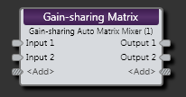
| Input nodes | Connection points for wiring input to the Gain-sharing Auto Matrix Mixer block |
| Output node | Connection points for wiring the Gain-sharing Auto Matrix Mixer input to specific outputs |
| <Add> nodes | Click to add another Input or Output node, or wire to the <Add> node to automatically create a new channel. |
(Hover over the thumbnail below to view the properties dialog box.)

| UI Element | Purpose |
|---|---|
| Crosspoint | Each square in the matrix where an input column and output row intersect) |
|
Crosspoint Priority (Manual and Linkable Control) |
Select to give an input priority. Provide end users with control over toggling the priority of an input by linking this Toggle Control to the Toggle Control of a DR2, DR3, or Logic In. |
| Priority Level | Set the level for the priority input(s). |
| Crosspoint Enable Checkbox | Select to include the input in the mix. |
| Input Mute (Manual and Linkable Control) | Mute this input. Provide end users with mute control by linking this Toggle Control to the Toggle Control of a DR2, DR3, or Logic In. |
| Input Signal | Lights when a signal is detected on this input, turns red if signal overload occurs. |
| Output Level (Manual and Linkable Control) | Control the volume of the entire mix for that output. Provide end users with control over the output volume by linking this Level Control to the Level Control of a DR1 or DR3. Change the range by clicking the Minimum or Maximum value (below the slider) and then typing new values in the edit box that appears. |
| Output Mute (Manual and Linkable Control) | Mute the mix output without changing the output level control. Provide end users with output mute control by linking this Toggle Control to the Toggle Control of a DR2, DR3, or Logic In. |
| Output Off @ Min Checkbox | When checked, causes the audio to mute completely when dialed to the low end of its range. |
| Overall Mute Checkbox | Mute all outputs from the Gain-sharing Auto Matrix Mixer block. Manual control only. |
 See Also