RAD26 Output Block
The RAD26 features
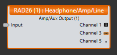
The RAD26 features two Amp outputs, and two Line outputs via Euro connectors on the back of the device and a headphone 1/8" mini TRS output that is accessible to end users from the bottom edge of the device.


The output properties dialog provides controls for adjusting Gain, Off @ Min, Invert, Block level mute, and individual mutes for the Amp pair, Line pair, and Headphone pair of outputs.
note: The value for the individual mutes (Amp, Line, and Headphone) are shared between both of the RAD26 output blocks.
- Click the Processing tab to open the Processing Workspace.
- In the palette area, click the I/O tab.
- In the Remote Audio Device Ports category, find the RAD26 device you want. Click and drag its Amp/Aux Output block into your Processing Map.
- Wire the appropriate output from your system to the block's Input node.
- (Optional) Customize the block name, input node, and/or output channel names by clicking the current name and then typing the custom name in the text box that appears. Click the X to save the name.
Open the Amp/Aux Output block's properties by double-clicking the block or hovering and clicking the properties icon that appears in the upper right of the block's title bar. From this dialog box, you can do the following:
- Set the level of the block's output by adjusting the Gain slider or entering a value in the edit box.
- Provide volume control to end users by linking one or more RAD26, DR1 or DR3 level controls to the block's Level Gain control. You can limit the range of end user volume control by adjusting the minimum and maximum values at either end of the level control. For example, to give the end user 24 dB of attenuation, set the minimum to -24 dB and the maximum to 0 dB. To change these values, click the minimum or maximum value displayed below the slider. An edit box displays in which you can set the Minimum and Maximum parameter values.
- Cause the audio to mute completely when dialed to the low end of its range by selecting the Off @ Min checkbox. Using the example range described above, checking Off @ Min provides continuous volume control from 0 dB to -23.9 dB and then mutes the audio completely once turned all the way down.
- Invert signal polarity to correct wiring errors implemented by accident or on purpose by unsuspecting installers or uninformed manufacturers. We still recommend fixing such wiring errors when they’re encountered, so future generations will look back on your installation as the ultimate example of truth, justice and proper polarity.
- Mute the output channel for the whole block—without changing the specified Gain value—by selecting the block's Mute checkbox. You can provide end users with control over this Mute parameter by linking the block's Mute control to a Logic In, DR2, or DR3 Toggle control.
- In addition to the block mute, the Amp, Line, and Headphone Output channels have individual linkable mutes. The mute values for these individual channels are shared - or always locked together - between both of the RAD26 output blocks.
- View meter data for the output signal.
- View the amplifier's limiter status on the red LED indicator.
| UI Element | Purpose |
|---|---|
| Input node | Connection point for wiring the input to the block |
| Amp Output (Channel 1) | The amp output channel connected to the corresponding RAD port on the HAL |
| Line Output (Channel 3) | The line output channel connected to the corresponding RAD port on the HAL |
| Headphone Output (Channel 5) | The headphone output channel connected to the corresponding RAD port on the HAL |

| UI Element | Purpose |
|---|---|
|
Gain (Manual and Linkable Control) |
Gain (both a manual and linkable control) sets the volume of all three RAD26 audio outputs. Also specified is the volume range with a Minimum and Maximum value. Change the volume by adjusting the slider or entering a dB value in the edit box. Provide end users with control over the volume by linking this Level Control to the Level Control of a DR1 or DR3. Change the range by clicking the Minimum or Maximum value and then typing new values in the edit box that appears. The meter displays signal data for the block output. Default Gain = 0.0 dB; Default Minimum = -33.0; Default Maximum = 12.0 |
| Off @ Min Checkbox | When checked, causes the audio to mute completely when dialed to the lowest end of its range. |
| Invert | When checked, inverts the signal polarity. |
| Limiter Active | The RAD26 limiter is a peak limiter that monitors the peak amplifier output current and prevents the RAD26 from exceeding the power limits of the RPI – Remote Power Injector, which supplies the power. This prevents the RAD26 from powering off due to exceeding the current delivery capability into current-hungry low impedance load, high voltage abuse. Limiter Active is lit (red) when the amplifier output is connected to a loudspeaker load of less than 8 Ω AND the RMS output level is approaching the RAD26’s maximum. Under these conditions, the RAD26 limiter turns down the output level of only the amplifier (not the headphone, not the Line output) to maintain a maximum output power level of 8 total watts across BOTH amp channels. |
| Amp Mute (Manual and Linkable Control) |
Mute BOTH channels of the block's amp output. Provide end users with a mute control for both amp outputs by linking this Toggle Control to the Toggle Control of a DR2, DR3, or Logic In port. note: The value for Amp Mute is always shared between both of the RAD26 output blocks. |
| Line Mute (Manual and Linkable Control) |
Mute BOTH channels of the block's line output. Provide end users with a mute control for both line outputs by linking this Toggle Control to the Toggle Control of a DR2, DR3, or Logic In port. note: The value for Line Mute is shared between both of the RAD26 output blocks. |
| Headphone Mute (Manual and Linkable Control) |
Mute BOTH channels of the block's headphone output. Provide end users with a mute control for both headphone outputs by linking this Toggle Control to the Toggle Control of a DR2, DR3, or Logic In port. note: The value for Headphone Mute is shared between both of the RAD26 output blocks. |
| Mute (Manual and Linkable Control) |
Mute the block's output without changing the Gain value. When the block is muted no audio passes regardless of the mute state of the individual Amp, Line, and Headphone mutes. Provide end users with output mute control by linking this Toggle Control to the Toggle Control of a DR2, DR3, or Logic In port. note: Unlike the individual RAD26 output mute controls that are each “locked” together in pairs (in “stereo” if you will), this Mute is only for one of the two audio channels sent to the RAD26. Since this single audio channel is sent to all three RAD26 outputs (amp, line & headphone), muting this control mutes all three “left” outputs (e.g., the odd-numbered RAD26 output channels); or for the second Amp/Aux Output block, all three “right” or even channels are muted. |
 See Also