DR4 Device Control Properties
- Click the Processing tab to open the Processing Workspace.
- On the Processing Palette, click the Control tab.
- In the Digital Remote Ports category (or Remote Audio Device Ports category as DRs can connect to those ports as well), click a DR4 device name, which is a hyperlink, to open its properties.
Provides a central location for:
- Adding controls to the DR4 device
- Modifying the configuration and the order of controls on the DR4 device.
- Deleting controls from the DR4 device
- Establishing a control links between the DR4 controls and other controls
- Viewing and changing each control's name
- Viewing and updating the current value of each control
- Adding each control to a preset and updating the baseline preset to current control settings (Logic Out only)
| UI Element | Purpose |
|---|---|
| Title Bar Name | Area at the top of the properties dialog box that displays the DR's Device Name as well as the HAL/EXP device model, the HAL/EXP port to which the DR is connected, and the DR model: 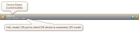 |
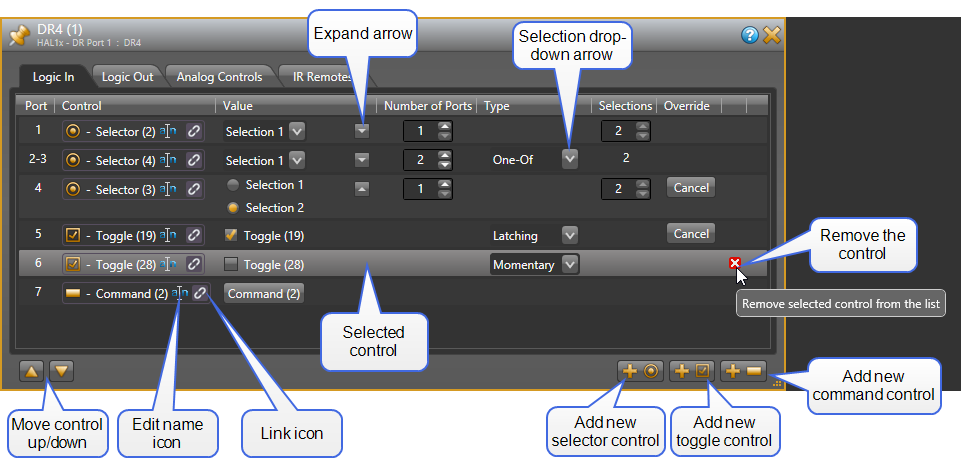
| Logic In panel |
This panel contains a list of Logic In controls configured for the DR4. The panel also shows buttons that allow you to move the selected control up or down in the list and to add a new selector, toggle, or command control to the end of the list. Toggle Controls
When a port is configured as a toggle control, the Type setting allows you to configure the type of physical switch that you are using. This setting is available only for toggle controls and allows you to select either Latching (default) or Momentary. See Momentary and Latching Toggle Configuration for more information about configuring these inputs. Command Controls
When a port is configured as a Command, the associated control in the Control palette of the Processing Workspace is a command type. There are no configuration options for this type of control. Selector Controls
When a port is configured as a Selector, the Number of Ports, Type, and Selections columns work together to allow you to configure the number of selections included in the associated selector control in the Processing Workspace. See the DR4, Logic Inputs section of Available Digital Remote Models for more information. To select a control, click on anywhere inside the control's row area in the list. |
| Port |
The Port number corresponds to the physical Logic In hardware port on the DR4. Eight ports are available and you can configure them in a variety of ways. |
| Control |
Shows the control type icon and name of the Logic In control as well as the standard control link icon. You can change the control name by clicking on the edit name icon. This name is intended to help you identify your controls when working in the Processing Map. You can link the control to another control of the same type on the Processing Map (for example, a Mute control). To do so, click, drag, and drop the Logic In link icon onto the link icon of the control on the Processing Map. |
| Value |
Displays and allows you to change the current state of the Logic In control according to its Control Type. Toggle: Check or uncheck the checkbox. note: You can change the state of a Logic In Toggle from within Halogen even when connected to HAL. When connected, a Latching type Logic In Toggle follows the state of the Logic In port, but you can override it by clicking on the toggle check box. This simulates changes from the physical switch (allowing you to test the control links). You can also do this when offline, but in this case, since there is no physical switch, Halogen does not consider the control to be overridden. Command: Assert the command by clicking on the button. Select: Change the selection using the drop-down menu. note: You can also view the selector value as a set of radio buttons by click on the 'expand' arrow on the far right of the Value column. |
| Number of Ports |
Use this to configure the number of physical DR4 Logic In ports to use for the selector. As you change this value, the Port column shows the ports currently allocated to each control. |
|
Type |
When the Logic In control type is toggle, Type allows you to view and set the toggle configuration: Latching or Momentary. Latching toggles are read-only while Momentary are not. When the control type is selector and the Number of Ports allocated to the control is greater than one, you have a choice for how the DR4 uses the Logic In signals to determine the selected item One-Of or Binary. One-Of: the DR4 treats each port as a separate selection input, where the lowest port is selection 1, the next lowest port is selection 2, and so on. Binary: the DR4 treats the set of ports as a binary number that determines the current selection. The lowest port is the least significant bit of the binary number while the highest port is the most significant bit. In operation, the DR4 makes the selected item of the associated selector control in the Processing Workspace according to the value of the binary number of the allocated ports. A binary value of 0 corresponds to the first selection, a binary value of 1 corresponds to the second selection, and so on. note: When you've allocated a single DR4 Logic In port to a selector, the Type is always binary, providing a two item selector control in the Control palette of the Processing Workspace. |
| Selections | This column shows how many selections are provided by the associated selector control in the Processing Workspace. For a One-Of configuration, this is always the same as the number of ports allocated to the control. For a Binary configuration, you can set this to match the number of selections that you desire, up to the maximum allowed by the binary number. |
|
Override |
The Cancel button appears when you have overridden the current state of the physical switch attached to the Logic In port. Click the button to revert to the actual state of the Logic In port. note: HAL cancels all read-only overrides when you disconnect Halogen or on HAL reboot. |
| Remove control icon | This icon appears when you hover with your mouse over a control item in the list and it is possible to remove the item. Click on the icon to remove the control from the list. |
| UI Element | Purpose |
|---|---|
| Title Bar Name | Area at the top of the properties dialog box that displays the DR's Device Name as well as the HAL/EXP device model, the HAL/EXP port to which the DR is connected, and the DR model: |
| Logic Out panel |
This panel contains a list of Logic Out controls configured for the DR4. The panel also shows buttons that allow you to move the selected control up or down in the list. To select a control, click on anywhere inside the control's row area in the list. |
| Port | The Port number corresponds to the physical Logic Out hardware port on the DR4. Eight ports are available and you can configure them in a variety of ways. |
| Control |
Shows the control type icon and name of the Logic Out control as well as the standard control link icon. You can change the control name by clicking on the edit name icon. This name is intended to help you identify your controls when working in the Processing Map. You can link the control to another control of the same type on the Processing Map (for example, a Mute control). To do so, click, drag, and drop the Logic Out control link icon onto the link icon of the control on the Processing Map. |
| Value |
Displays and allows you to change the current state of the Logic Out control according to its Control Type. Toggle: Check or uncheck the checkbox. Select: Change the selection using the drop-down menu. note: You can also view the selector value as a set of radio buttons by click on the 'expand' arrow on the far right of the Value column. |
| Control Type |
Allows you to view and change the control type of the Logic Out port - Toggle or Two Position Selector.
|
|
Preset icon and Update Baseline Preset button |
The preset icon, When you click on the Update Baseline Preset button, |
 , allows you to add one or all Logic Out controls to a preset. When you drag the icon in the header area and drop it on a valid preset drop target, Halogen adds all of the Logic Out controls to the preset. If you drag the preset icon from an individual Logic Out control, Halogen only adds that control to the target preset.
 , Halogen updates the baseline preset for one or all Logic Out controls, setting the baseline preset to the current control values. When you click the button in the header area, Halogen updates the baseline preset for all Logic Out controls. If you click the button for an individual Logic Out control, Halogen only updates the baseline preset for that control.
| UI Element | Purpose |
|---|---|
| Title Bar Name | Area at the top of the properties dialog box that displays the DR's Device Name as well as the HAL/EXP device model, the HAL/EXP port to which the DR is connected, and the DR model: |
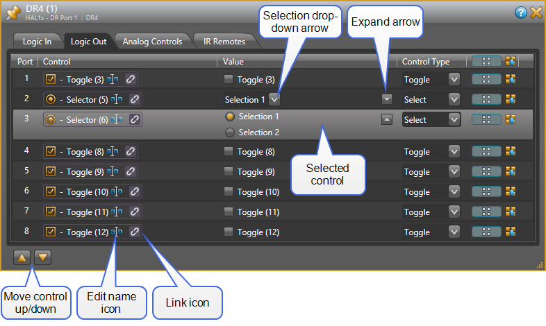
| Analog Controls panel |
This panel contains a list of Analog Controls configured for the DR4. The panel also shows buttons that allow you to move the selected control up or down in the list. To select a control, click on anywhere inside the control's row area in the list. |
| Port | The Port number corresponds to the physical Analog Control hardware port on the DR4. Each port provides a single read-only level control, available in the Control palette of the Processing Workspace. The Analog Control ports have no configuration options. |
| Control |
Shows the control type icon and name of the Analog Control as well as the standard control link icon. You can change the control name by clicking on the edit name icon. This name is intended to help you identify your controls when working in the Processing Map. You can link the control to another control of the same type on the Processing Map. To do so, click, drag, and drop the Logic Out control link icon onto the link icon of the control on the Processing Map. |
| Value |
Displays and allows you to change the current state of the Level control. Set a new value by clicking on the slider and moving it to a new position. Alternatively, enter a new value into the text box or click the up or down arrow to the right of the text box. note: You can change the value of an Analog Control from within Halogen even when connected to HAL. When connected, an Analog Control follows the state of the DR4 port, but you can override it by changing the level value. This simulates changes from the physical Analog Control device (allowing you to test the control links). You can also do this when offline, but in this case, since there is no physical DR4, Halogen does not consider the control to be overridden. |
|
Override |
The Cancel button appears when you have overridden the current state of the physical Analog Control port. Click the button to revert to the actual state of the DR4 port. note: HAL cancels all read-only overrides when you disconnect Halogen or on HAL reboot. |
| UI Element | Purpose |
|---|---|
| Title Bar Name | Area at the top of the properties dialog box that displays the DR's Device Name as well as the HAL/EXP device model, the HAL/EXP port to which the DR is connected, and the DR model: |
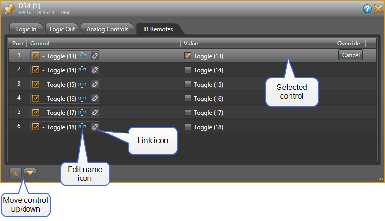
| IR Remotes panel |
This panel contains a list of IR Remote controls configured for the DR4. The panel also shows buttons that allow you to move the selected control up or down in the list. To select a control, click on anywhere inside the control's row area in the list. |
| Port |
The Port number corresponds to the physical IR Remote hardware port on the DR4. Each port provides a single read-only toggle control, available in the Control palette of the Processing Workspace. When an IR2 device is properly connected to an IR Remote port, the associated toggle control in the Processing Workspace is 'checked' when the IR receiver is sensing infrared (wall open) and 'unchecked' otherwise (wall closed). |
| Control |
Shows the control type icon and name of the IR Remote control as well as the standard control link icon. You can change the control name by clicking on the edit name icon. You can link the control to another toggle control on the Processing Map (for example, a toggle wall control in a Room Combine block). To do so, click, drag, and drop the IR Remote control link icon onto the link icon of the control on the Processing Map. |
| Value |
Displays and allows you to change the current state of the Toggle control: check or uncheck the checkbox. note: You can change the state of an IR Remote Toggle from within Halogen even when connected to HAL. When connected, an IR Remote Toggle follows the state of the IR Remote port, but you can override it by clicking on the toggle check box. This simulates changes from the physical IR Remote device (allowing you to test the control links). You can also do this when offline, but in this case, since there is no physical IR Remote, Halogen does not consider the control to be overridden. |
|
Override |
The Cancel button appears when you have overridden the current state of the physical IR Remote port. Click the button to revert to the actual state of the IR Remote port. note: HAL cancels all read-only overrides when you disconnect Halogen or on HAL reboot. |