Toggles
This section explains how to integrate HAL toggle controls with buttons on an AMX touch panel by examining a couple of applications: a toggle preset button and a wall toggle button on a touch panel. We start by dissecting the code for the HAL toggle controls and touch panel toggle buttons. Then we demonstrate how to bind HAL toggle controls to buttons in the touch panel user interface.
Toggles in a HAL system have only an on or off state. They are represented as checkboxes in the Halogen software and DR remotes. Because toggles only have two states they are modeled as integers with values of 0 and 1 in NetLinx. The example program provides code for handling toggle button events from the touch panel and parsing toggle message strings from a HAL. Let’s take a look at it.
Open the Main.axs source file in NetLinx Studio. Find the DEFINE_CONSTANT section of the program. It contains some toggle-related constants:
BTN_MUTE_ALL = 4
BTN_WALL_OPEN = 5
…
INTEGER nToggleChannels[] = { BTN_MUTE_ALL, BTN_WALL_OPEN }
This code says that there are two HAL toggle controls in this program and that their touch panel device channel numbers are 4 and 5. The 4 and the 5 are also HAL control numbers used to uniquely identify controls on the HAL. These control numbers appear in the External Control Systems dialog of the Halogen software. Matching device channel numbers with HAL control numbers makes programming multiple HAL toggle controls easy.
The example toggle code is reusable across applications. If you want more toggle buttons on the touch panel just add more device channel numbers to the nToggleChannels array. Coding a new toggle application is simply a matter of matching HAL toggle control numbers in Halogen with newly-added toggle button device channel numbers in AMX.
There is one button event handler for all of the toggle buttons on the touch panel. Feel free to copy and paste event handler into your own programs.
BUTTON_EVENT[dvTP, nToggleChannels]
{
  RELEASE:
  {
    nToggleIndex = GET_LAST(nToggleChannels)

    if (nToggleIndex > 0 &&
        nToggleIndex <= length_array(nToggleChannels))
    {
      bToggleValues[nToggleIndex] =
        !bToggleValues[nToggleIndex]

      Send_String dvHAL, "'<T&',
                  itoa(nToggleChannels[nToggleIndex]), '&',
                  itoa(bToggleValues[nToggleIndex]), '>'"
    }
  }
}
A button event handler does not have to take a single device channel as its channel reference parameter. It can accept an array of device channel numbers. In the case of our touch panel’s toggle button event handler, all of the toggle buttons’ device channel numbers are passed in through the nToggleChannels argument. The handler knows which toggle button on the touch panel fired the event because the GET_LAST call returns the index of that button in the nToggleChannels array.
Whenever a toggle button on a touch panel is released the toggle button event handler sends a message string with a new toggle value to the HAL. These ‘set toggle’ messages contain a toggle control type, HAL control number and value. Valid ‘set toggle’ messages for the two HAL toggle controls in this example would be <T&4&0>, <T&4&1>, <T&5&0> and <T&5&1>.
note: Refer to Appendix A External Control Message Protocol for more information on toggle messages.
The HAL sends these same ‘set toggle’ messages to the controller when another client changes a HAL toggle control value. Here is the STRING event handler code to parse incoming HAL toggle control values.
active(find_string(cData, '<T&', 1)):
{
  remove_string(cData, '<T&', 1)

  nToggleIndex = FindToggleIndex(atoi(cData))

  remove_string(cData, '&', 1)

  if (nToggleIndex > 0 &&
      nToggleIndex <= length_array(nToggleChannels))
  {
    bToggleValues[nToggleIndex] = atoi(cData)
  }
  remove_string(cData, '>', 1)
}
The Mainline contains feedback statements for all the defined toggles. These feedback statements update the visible state of toggle buttons on the touch panel in response to HAL toggle control value changes triggered by touch panel button presses or messages from the HAL.
for (nToggleIndex = 1;
     nToggleIndex <= length_array(nToggleChannels);
     nToggleIndex++)
{
   [dvTP, nToggleChannels[nToggleIndex]] =
            bToggleValues[nToggleIndex]
}
The controller requests HAL toggle control values from the HAL upon connecting. This ensures that the toggle buttons on the touch panel are in sync with the live toggle values on the HAL. The controller does this by sending ‘get toggle’ messages to the HAL when the ONLINE event is fired. These ‘get toggle’ messages consist of a toggle control type and HAL control number. See the toggles for loop in the client’s ONLINE event handler for how to encode and send them.
for (i = 1;
     i <= length_array(nToggleChannels);
     i++)
{
   Send_String dvHAL, "'<T&', itoa(nToggleChannels[i]), '>'"
}
The ‘get toggle’ messages for this example are <T&4> and <T&5>. Upon receipt of these ‘get toggle’ messages the HAL responds with ‘set toggle’ messages for those two HAL toggle controls.
Toggle Presets
This example demonstrates how to get a toggle button on a touch panel to activate and deactivate a preset on a HAL. The example Halogen configuration file contains a toggle preset for muting and unmuting all the audio outputs on the HAL. This Mute All Preset is linked to a HAL Control Systems toggle control named Mute All Toggle Control. Toggling the HAL toggle control activates or deactivates the preset.
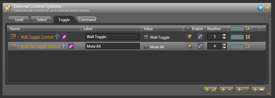
Open the ControlSystemSample.hal example configuration file in Halogen. Switch to the Processing workspace by clicking on the Processing tab. Next, open the External Control Systems dialog and select the Toggle tab. Notice that the Mute All Toggle Control is assigned a HAL control number of 4. For this application to work, the Mute All Toggle Control number needs to match the device Channel Code of the Mute All button on the touch panel. This is what is meant by matching HAL control numbers with device channel numbers.
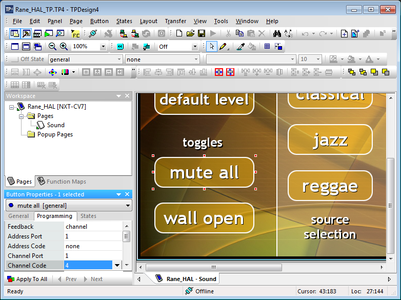
Open the Rane_HAL_TP.tp4 design file in TPDesign. Next open the Sound page window to view the example touch panel design. Select the Mute All button in the Sound page window then select the Programming tab in Button Properties. Notice that the Channel Code for the Mute All button on the touch panel is set to 4 to match the HAL Mute All Toggle Control number and the Feedback is set to channel for latching. The Mute All button appears lighter on the touch panel when the channel is off and darker when the channel is on.
Verify that the Connected status indicator in the upper right corner of the touch panel says Connected. Refer to the Troubleshooting section if it says Disconnected. Press the Mute All button on the touch panel. The button will remain in its new on or off state after you lift your finger. This is what is meant by latching. Watch the Active state of the Mute All Preset in Halogen as you press the button on the touch panel. Then toggle the Mute All Preset from Halogen to see that the Mute All button and Lounge bar graph on the touch panel respond.
note: Refer to Appendix B Using PuTTY to Test External Control Systems for help with debugging if the system does not behave as described here.
Wall Toggles
This example demonstrates how to get a toggle button on a touch panel to open and close a movable wall in a HAL room combine block. The example Halogen configuration file contains a room combine block with two rooms A and B. The movable wall in between these two rooms is linked to a HAL Control Systems toggle control named Wall Toggle Control. Toggling the HAL toggle control opens and closes the wall.
Open the ControlSystemSample.hal example configuration file in Halogen. Switch to the Processing workspace by clicking on the Processing tab. Next, open the External Control Systems dialog and select the Toggle tab. Notice that the Wall Toggle Control is assigned a HAL control number of 5. For this application to work, the HAL Wall Toggle Control number needs to match the device Channel Code of the Wall Open button on the touch panel.

Open the Rane_HAL_TP.tp4 design file in TPDesign. Next, open the Sound page window to view the example touch panel design. Select the Wall Open button in the Sound page window then select the Programming tab in Button Properties. Notice that the Channel Code for the Wall Open button is set to 5 to match the HAL Wall Toggle Control number and the Feedback is set to channel for latching.
Touch panel buttons can display different text for their on and off states. That often makes a lot of sense in the context of toggle buttons. Double-click the Off state image for the Wall Open button in the State Manager. This will pull up the Off state Button Properties for that button. From there you can change that button’s Off state text to say “wall closed” if you prefer.
Verify that the Connected status indicator in the upper right corner of the touch panel says Connected. Refer to the Troubleshooting section if it the status indicator says Disconnected. In Halogen, double-click the Room Combine (1) block in the Halogen Processing map then select the Layout and Control tab in the Room Combine (1) dialog. Watch the wall between rooms A and B open and close in Halogen as you press the Wall Open button on the touch panel open and closed. Now toggle the wall open and closed from the Room Combine (1) dialog in Halogen and watch that same button turn on and off on the touch panel.
note: Refer to Appendix B Using PuTTY to Test External Control Systems for help with debugging if the system does not behave as described here.