Introduction to Halogen Conference Room Combine
Now that we are getting comfortable with the basics, it’s time to dive into something that many fear and few have attempted: what would it take to include conferencing in a room combine application? It’s not that hard to conceptualize, but often difficult to implement using typical tools. All you need to do is properly combine microphones, AV and from far end inputs, acquire an appropriate reference and output signals to the appropriate rooms and to far end destinations.
Halogen provides a highly integrated Conference Room Combine block that greatly simplifies this process. The image below shows a basic conference room combine configuration. For this example the number of microphones and AV sources is limited to one per room and the number of rooms is limited to two in order to simplify the configuration and allow us to focus how the system works. The same principles apply as you add more rooms, microphones and AV sources.
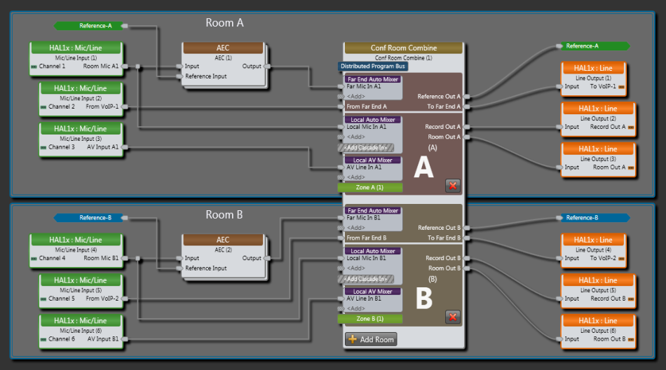
Those familiar with a standard Halogen Room Combine block will notice some similarities. The Conferencing Room Combine block includes the same Distributed Program Bus, Local Automixer (Auto Mixer), Local AV Mixer (Mixer), Paging Zone, Room Out and Record Out and base rooms combine in the same manner. In the Conference Room Combine, each base room also includes a Far End Auto Mixer, a From Far End input, a To Far End output and a Reference Out output.
- Far End Auto Mixer is where you connect any microphone that needs to be heard at a far end. To reduce echo, this configuration includes an AEC block before each Far End Auto Mixer input. You may connect a microphone to a Far End Auto Mixer, Local Auto Mixer or both. Connecting microphones to the Local Auto Mixer allows them to be heard in the local room.
- From Far End is where a From Far End conference connection into a room is made. This may be from VoIP, Video Codec, POTs or any other far end conference source. When combining rooms, not all rooms need to have a conference input, but more than one room may have this input as in this example. When rooms combine, the room combine block mixes together all of the From Far End signals as we’ll discuss later.
- Reference Out provides a reference signal that feeds an AEC reference input. The room processor derives this signal by mixing local AV and from far end sources as in earlier examples. An identical reference is sent to each room when rooms are combined. If unique signal processing is applied to each base room as shown on page 1, each base room reference needs to have this same processing applied before being used.
- To Far End provides a signal for a far end. As with the reference output, the block sends an identical signal to all combined rooms. In the above example there is a VoIP line in each room and either may require a To Far End signal.
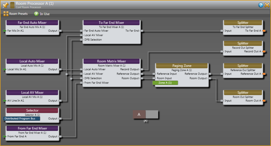
A look inside a Room Processor provides a clearer view of its structure. It shows a typical room combine assortment of I/O plus the additional I/O required for conferencing. As with the standard Room Combine block, a similar Room Processor exists for Room A, Room B and Room A+B.
The following figure shows the Room A+B processor. Note that signals from the two rooms combine in the Far End Auto Mixer, the Local Auto Mixer, the Local AV Mixer and the From Far End Mixer blocks.
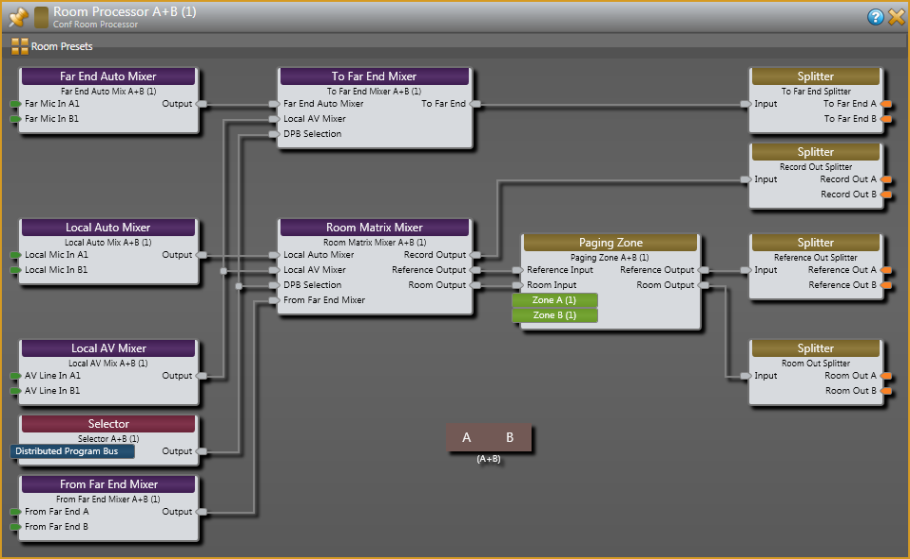
The Far End Auto Mixer combines all connected microphones from both rooms needed for the far end. The To Far End Mixer allows a custom mix of far end microphones, Local AV sources and Distributed Program Bus (DPB) selection. The block splits this composite To Far End signal out to each room as shown. How the Record Out, Reference Out and Room Out are mixed is better understood by taking a closer look at the Room Matrix Mixer which is central to all conferencing room processors.
The following figure shows the properties dialog for this mixer:
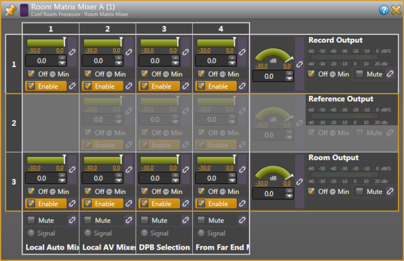
The Record Out signal consists of a unique mix of the four available sources. You can use this signal for recording an event or supplying audio to an overflow room. You could also use this signal in conjunction with the Room Out to provide one zone with Voice Lift and another without.
The Room Out signal also consists of a unique mix of the four available sources.
Remember we discussed a need for the AEC reference to match what is sent to a room? In the case of the Room Matrix Mixer, this means that if you add a source to a room mix, the same needs to happen in the reference mix. In a similar way, if you delete a source from the room mix, you also need to delete it from the reference mix. In addition, you also need to make corresponding changes to the reference signal when adjusting a crosspoint level or room output level. For this reason, the Room Matrix Mixer’s crosspoint mix levels and output level control follow the settings for the Room Out. The Room Matrix Mixer dialog shows Reference Out controls in half-tone to indicate that you may not adjust them independently from the Room Out mix. Displaying the reference controls in this way also clearly shows that the block applies identical settings to both the Room Out and the Reference Out. When linked level controls are required for a room, you should link to Level controls in the Room Matrix Mixer to ensure that Room Out and Reference Out track.
As in our previous examples, we do not include near end microphones in the reference. If your application is suitable for near end microphones to be included in the reference, you can use the room output for both the room and the reference. As shown earlier, the mix without local microphones may be appropriate for use in loudspeakers co-located with a head table.
Once Room Out and Reference Out signals leave the Room Matrix Mixer, we still need to ensure that they track each other. In the Room Processor, a Paging Zone block follows the Room Matrix Mixer. As with a standard Halogen Room Combine block, paging combines as rooms combine. Paging into a room ducks all other signals by a set amount and adds paging audio to the room. When this happens, the reference needs to follow. The Conferencing Room Combine block provides a special “tracking” Paging Zone block able to duck and add page audio to the reference as well as the room. Note that this behavior is required whether the Reference Out is used for an AEC reference, mix-minus zone or both.
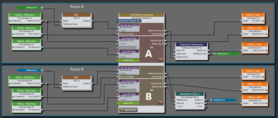
Now is a good time to discuss why the block sends an identical reference signal to each room. Consider the configuration shown below. For demonstration purposes, this configuration includes different processing for each room output (often a real world requirement). In particular, Room-A includes a compressor while Room-B includes a PEQ. As we’ve learned all along, the AEC reference signal must always match the room output signal, so the configuration uses a Tracking Compressor in Room-A to ensure that the reference matches the room output. In a similar manner, the configuration uses a Multichannel PEQ block in Room-B.
When you combine the two rooms, the Conferencing Room Combine block’s Reference Out A and Reference Out B are the same signal. The additional processing that creates Reference A and Reference B is different. Deciding which reference to use in each of the AEC blocks depends on where the microphones for the far end are located. Use Reference A if all microphones are located at a head table in Room A. Use Reference B if all microphones are located at a head table in Room B. If some microphones are in Room A and some in Room B, you may use both references -- with Reference A sent to the AEC blocks for microphones located in Room A and Reference B sent to the AEC blocks located in Room B as shown below.