Basic Halogen Conferencing Configuration
The following Halogen processing map demonstrates a simple conference configuration. Remember that a complete conference system employs a similar configuration for near-end and far-end rooms:
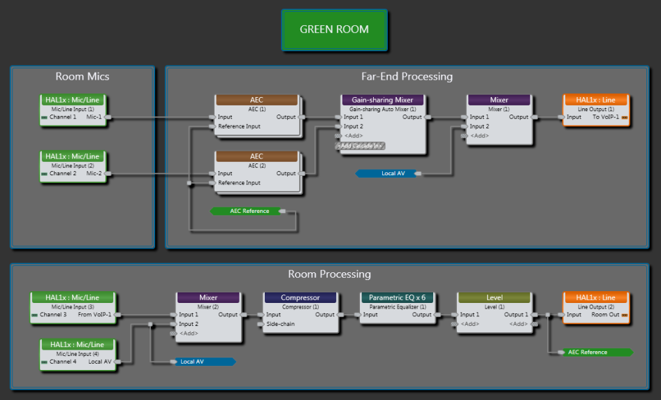
This configuration is more advanced than the basic two room conference diagramed in the AEC Introduction, but the same basic principles apply. This configuration may be expanded to support any number of microphones and AV sources as well as a variety of room processing. Eight channels of drag and drop AEC are available in an EXP7x Halogen expansion device. All other processing blocks in these examples are available in a HAL1x device.
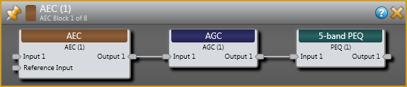
In this example, From VoIP 1 is a signal from the far-end and To VoIP 1 is the signal returned to the far-end. These signals are used to establish a duplex connection between the two conference rooms. An AEC block is used for each near-end microphone. Each AEC block includes AEC with ambient noise reduction, Automatic Gain Control (AGC) and Parametric Equalizer (PEQ). As shown in the following image, AGC and PEQ functions follow AEC processing, allowing adjustment without interfering with room modeling.
Following the AEC blocks is an automatic Gain-sharing Mixer. This mixer distributes gain between any number of microphones based on received signal amplitude and priority
The configuration above does not require local speech reinforcement so inputs to the room are simply a signal from the far-end and local AV sources. Output to the far-end consists of echo free speech from the two near-end microphones and local AV sources.
Additional processing for the room includes Compression, PEQ and Level control. Earlier we mentioned the importance of a reference signal accurately representing the signal output to a room in order to maintain an accurate room model for the AEC algorithm. The configuration satisfies this requirement by locating the AEC Reference after this additional processing. When providing a linked level control for the room, it is important to include the level control before the reference so that the room output signal and the reference track each other.