Knowledge Base
Perfect-Q™, the Next Step in Graphic EQ Design
Perfect-Q™, the Next Step in Graphic EQ Design
Rick Jeffs, Ray Miller, Dennis Bohn, Rane Corporation
RaneNote 154, written 2003
- What You See Is (Really) What You Get
- Independent Band Adjustment
- Constant Bandwidth For All Slider Settings
- Minimum Phase Response
- Eliminates Band Interaction Overload
Pursuit of the Unreachable Star
The quest for absolute truth in graphic equalizer slider position has a long history and Rane helps with a giant step forward. Using advanced DSP algorithms, Rane Corporation introduced an entirely new generation of graphic equalizers that realize the dream of having the output magnitude response correspond exactly to the front panel settings*. Extensive development resulted in this new technology trademarked "Perfect-Q," because that is what it does: calculates the perfect Q required to create the exact response dictated by the front panel slider positions.
There is irony in knowing that improving Rane's much praised constant-Q technology required switching to variable-Q technology to perfect the response vs. slider position problem. The popularity of Q-terminology is unfortunate since what is meant is bandwidth. In hindsight, naming the complementary technologies "constant bandwidth" and "proportional bandwidth" would have been better choices, because these terms identify the solutions more accurately.
Rane championed constant-Q designs beginning in 1982 as a better solution to the problem of slider-based graphic equalizers. Constant-Q gave a more honest front panel representation than proportional-Q. It minimized what Rane called "equalizing the equalizer," i.e., having to go back and readjust adjacent sliders to counteract the problem of interaction between bands. This is the phenomena where adjusting one band causes similar, but reduced, adjustment to adjacent (and even further out) bands. For example, if you boosted 800 Hz by a couple of dB, you would inadvertently boost the energy centered at 630 Hz and 1000 Hz. Constant-Q interacted less than proportional-Q and now Perfect-Q eliminates this problem.
Perfect-Q Advantages
The advantages of the Perfect-Q design go far beyond yielding a more accurate picture; it provides a degree of adjustment never before possible. Crucial subtle refinements of frequency response are for the first time possible, allowing for an unequaled ease of operation and clarity of sound reproduction. Changing a 1/3-octave setting changes only that setting. This is unlike any other graphic EQ available (i.e., one providing real mechanical front panel slide controls as of January, 2003).
DSP Provides the Solution
DSP allows more flexible processing than analog and permits delaying final filter parameters until the actual user settings are known _ something not possible with analog. This gives the power to build an EQ that has an ideal response. The idea driving development of Perfect-Q is the same as constant-Q: constant bandwidth for each EQ band no matter what the setting, but DSP allows doing things that aren't practical (or in some cases even possible) in analog circuits, producing an even better outcome as demonstrated by these Perfect-Q characteristics:
- What you see is (really) what you get.
- Constant bandwidth for all slider settings.
- Adjusting one band does not change neighboring bands.
- Improved phase response due to eliminated interactions.
- No band interaction overload problems.
Graphic Details
Early EQs used passive analog networks resulting in a proportional-Q (also known as variable-Q; "Q" is inversely proportional to filter bandwidth) response, that is, the filter bandwidth became wider or narrower depending upon the slider setting. While producing smooth alteration of frequency response, proportional-Q designs have significant interaction between adjacent bands. For certain applications this interaction results in a "sound" some listeners grew to appreciate, even at the expense of poor correlation between overall response and slider position. Figure 1 shows two adjacent sliders boosted 6 dB, with the resultant proportional-Q response. As shown the proportional-Q graphic equalizer's front panel is a poor representation of the true frequency response curve. Front panel says +6 dB, but the real output is +9 dB.
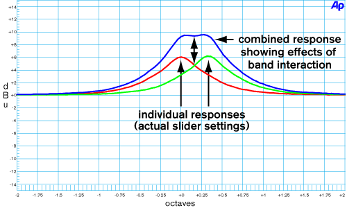
Figure 1. Band interaction of 1/3-octave Proportional-Q filters
By the 1970s it was clear that a constant-Q design would come a lot closer to the ideal. The use of active filters greatly increased the designer's ability to realize new filter topologies and, in 1981, three constant-Q, one-third-octave graphic equalizers were concurrently designed. While a significant improvement, the results were not ideal. Figure 2 shows the response of a constant-Q design with two adjacent sliders boosted 6 dB. While band interaction is significantly reduced, ripple between bands is increased.
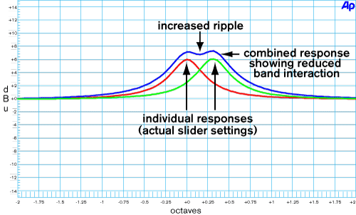
Figure 2. Band interaction of 1/3-octave Constant-Q filters
Interpolating Constant-Q, developed to reduce the ripple, works quite well, however band interaction is increased, and the overall output amplitude is nearly as bad as proportional-Q. Figure 3 shows it is narrower, more closely approximating the front panel's 2/3-octave width, but the amplitude is nearly +9 dB.
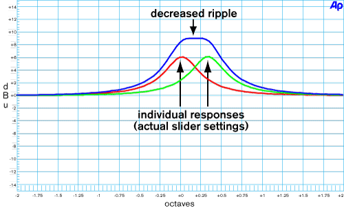
Figure 3. Band interaction of Interpolating Constant-Q filters
It's not Constant _ not Proportional _ It's Perfect!
As stated earlier, DSP allows filter technology not possible with analog designs. Ray Miller, one of Rane's distinguished DSP engineers extensively researched filter band interaction and developed new ways of preventing it.
Perfect-Q features virtually no band interaction and extremely low ripple between adjacent bands. The result: the world's first graphic equalizer whose output response precisely matches the front panel slider settings, dramatically shown in Figures 4 and 5.
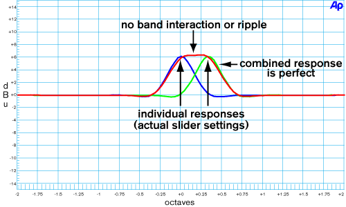
Figure 4. Graphic response of Perfect-Q filters
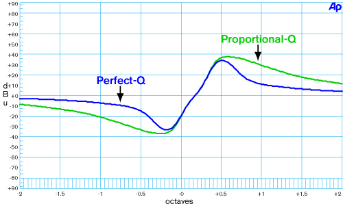
Figure 5. Phase response of Figures 1 and 4.
What you see is what you've cut--or boosted
If that doesn't impress you, look at Figure 6 where an example of DEQ 60 slider positions are lined up with the frequency responses corresponding to the Perfect-Q and Proportional-Q settings. There's a scoop around 250 Hz to remove some low-mid woof, a few notches around 1 kHz and 2 kHz for feedback control, and a dip in the 8 kHz region to tame a pesky high frequency hot spot. Note the difference between the two curves, especially the interactions between adjacent bands in the low-mids and the 6 dB offset at 1.25 kHz. Which EQ curve looks more like the front panel slider positions? Which one is perfect?
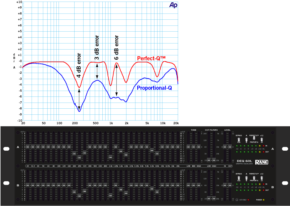
Figure 6. Perfect-Q versus Proportional-Q matching equalizer settings
Getting From There to Here
Condensed to its essence, Perfect-Q is a proprietary method for linearizing filter band interaction using variable-Q techniques, which makes getting from settings to response very accurate.
With that as the end, let's go back to the beginning and see how we got here:
Graphic equalizers are constructed from a set of filters evenly spaced on a logarithmic frequency scale, providing a relatively narrow-band adjustment of the audio spectrum. Typically there is a one-third-octave spacing. Each filter affects a band of frequencies centered about the specified center frequency, and is set flat, having no effect, or adjusted to boost or cut, amplifying or attenuating its frequency band.
Graphic equalizers suffer from overlapping band problems, where adjusting one band adjusts adjacent bands to a lesser -- but significant -- extent, resulting in a frequency response not matching the settings. Creating a response matching the settings makes equalizers easier to use.
Various techniques exist to achieve this aim: you can use complex filters, which have negligible effect on adjacent bands, however narrow bandwidths require lots of expensive computing power. Alternatively, adding extra filters can compensate for the interaction. Or, most commonly, adjusting the filter settings on the fly to approximately yield the desired response.
Several techniques can accomplish this last method. Different iterative methods exist, where adjustments are made, the error analyzed, then adjustments are made again, and so forth, until the error is sufficiently small. This is what a person who could see the amplitude vs. frequency response would do. Although a computer does it much faster, this equalizing-the-equalizer procedure still results in an undesirable time lag between changing settings and the desired response.
Linear Response Changes
Although not particularly obvious, graphic equalizer bandpass response is, in general, not linear. What this means is that when the center frequency amplitude is changed the filter skirts do not necessarily change in a linear manner. If it were a linear response then boosting the center frequency amplitude would result in a boosting of the skirts a known and predictable (key words) amount that was a linear factor of the amount of center boost. For example look at Figures 7 and 8. Figure 7 shows that boosting the center in 4-dB steps results in points located 1/3-octave away being boosted, first around 1-dB, then about 2-dB and for the last 4-dB step nearly 3-dB. Contrast this with the Perfect-Q linear response shown in Figure 8, where the same points increase the same amount for each 4-dB increase.
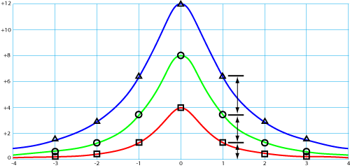
Figure 7. Constant-Q Nonlinear Response.
The setting is adjusted in linear steps: 4, 8, and 12 dB, and we see the resulting response curves. Symbols are shown at 1/3-octave intervals. For a constant-Q filter, the level 1/3-octave away (shown as 1) is not a linear function of the setting, as we see by the uneven spacing.
Figure 8. Perfect-Q Linear Response.
The Q has been adjusted such that the level 1/3-octave away (shown as 1) is a linear function of the setting.
In previous graphic equalizer designs the interaction acts like a linear system for small settings, but not for large ones. The results are good as long as the filters are not boosted or cut by large amounts; in that case the result is a compromise, but it is better than uncorrected. To linearize the system the filters must be cascaded. This results in the dB (logarithmic level) responses of the filters summing together to form the composite response; otherwise phase shifts between filter sections complicate things.
Perfect-Q takes a different approach. It adjusts the filter Q, or bandwidth, as a function of boost/cut amount, in such a way as to make the interaction linear, and thereby much easier to correct. The frequencies of the two filters directly adjacent to a given filter are given priority. The interactions at those two frequencies are made perfectly linear, which makes the interactions at more distant frequencies more nearly linear, and so on. Once the response is linear it is a straightforward, although complex, mathematical matter to check the user setting and subtract the resultant interaction so only the intended change is made.
Perfect-Q Availability
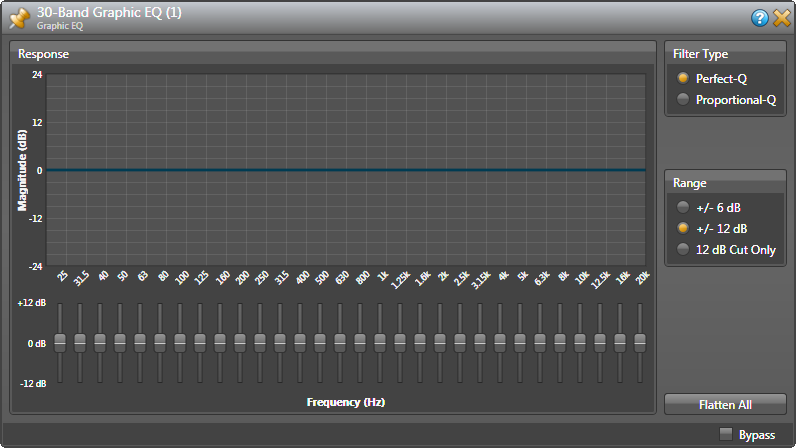
This technology is used in the DEQ 60L Digital Graphic Equalizer -- a 2-channel 30-band 1/3-octave design with conventional slider controls (part of Rane's analog-controlled digital series).
Perfect-Q is available in all HAL Multiprocessors as an option in Halogen's Graphic EQ processing block.
Proprietary Rights
All techniques and algorithms discussed in this article are covered by U.S. Patent 7,266,205 granted to inventor Ray Miller and assigned to Rane Corporation. International patent pending.
*Acknowledgement is given to the first products addressing this issue: the IEQ Smartcurve by ART and the TC 1128 by T.C. Electronics both introduced in 1987, and to the latest work achieving similar results by Lake Technology in 2002 as part of their proprietary loudspeaker processor designed for Clair Brothers, named Clair iO, and available now to the general public as the Lake Contour loudspeaker processor. This processor exhibits true arbitrary magnitude response for all equalizer types. Rane's unique technology is developed specifically for graphic equalizer use (i.e., one providing real mechanical front panel slide controls), to faithfully duplicate the front panel fixed-frequency slider positions.
 "Perfect-Q, the Next Step in Graphic EQ Design" This note in PDF.