Knowledge Base
Grounding and Shielding Audio Devices
?
Grounding and Shielding Audio Devices
Steve Macatee, Rane Corporation
RaneNote 151, written 1995, revised 2002
- Splitting Signals
- Subwoofing in Mono
- Unbalanced Summing
- Balanced Summing
- Output Impedances
Introduction
Now that the Audio Engineering Society has adopted the "pin 2 is hot" standard, the question of what to do with pin 1 is being addressed. A recommended practices document is being created covering interconnection of professional audio equipment. How and where to connect pin 1 is too complex to be issued as a standard; thus only a recommended practice is being developed. The recommended practices may affect manufacturers who choose to follow them.
Many shield-wiring practices exist in the audio industry today. The majority of available literature on the subject prescribes clear solutions to any wiring problem, yet problems are rampant due to inconsistent variations on the well-documented ideal. Two clear groups have developed on either side of a hard-to-straddle fence -- the balanced world and the unbalanced world.
Over the years, the declining cost of professional audio equipment has facilitated its use in more and more home studio environments. As home studios incorporate professional, balanced equipment into their systems, the unbalanced and balanced worlds collide. Home studios adding balanced equipment to their traditionally unbalanced gear also add connectivity problems. Professional users never consider unbalanced gear, yet still have connectivity problems.
The performance of any interconnection system is dependent on input/output (I/O) circuit topologies (specific balanced or unbalanced schemes), printed circuit board layout, cables and connector-wiring practices. Only wiring practices, both in the cable and in the box, are covered here. The I/O circuit topologies are assumed ideal for this discussion to focus on other interconnection issues.
The Audio Engineering Society recommendation will address a simple issue, the absurdity that one can not buy several pieces of pro audio equipment from different manufacturers, buy off-the-shelf cables, hook it all up, and have it work hum and buzz-free. Almost never is this the case. Transformer isolation and other interface solutions are the best solutions for balanced/unbalanced interconnections, though they are too costly for many systems. Even fully balanced systems can require isolation transformers to achieve acceptable performance. Some consider isolation transformers the only solution. These superior solutions are not covered here.
Another common solution to hum and buzz problems involves disconnecting one end of the shield, even though one can not buy off-the-shelf cables with the shield disconnected at one end. The best end to disconnect is unimportant in this discussion. A one-end-only shield connection increases the possibility of radio frequency (RF) interference since the shield may act as an antenna. The fact that many modern day installers still follow the one-end-only rule with consistent success indicates that acceptable solutions to RF issues exist, though the increasing use of digital technology increases the possibility of future RF problems. Many successfully and consistently reduce RF interference by providing an RF path through a small capacitor connected from the lifted end of the shield to the chassis.
The details of noise-free interconnections and proper grounding and shielding are well covered in other literature. They are not revisited here. Readers are encouraged to review the References listed for further information. Most of these materials have been applicable in the audio industry for well over 60 years, though they have not been implemented or embraced by many.
Balanced vs. Unbalanced Shields
For the ensuing discussion, the term shield is qualified with the description balanced or unbalanced. An unbalanced return conductor physically resembles a shield and provides shielding for electric fields, but magnetic fields are not shielded. Though this is also true for balanced shields, the twisted-pair construction of balanced cables provides much greater immunity to magnetic field interference. Unbalanced cable shields also carry signal in the form of return current, further alienating unbalanced shields from "true" shields. Shield is defined by Ott [1] as "... a metallic partition placed between two regions of space. It is used to control the propagation of electric and magnetic fields from one place to another." Balanced interconnection provides the superior interface of the two.
The "Pin 1" Problem
Many audio manufacturers, consciously or unconsciously, connect balanced shields to audio signal ground; pin 1 for 3-pin (XLR-type) connectors, the sleeve on 1/4" (6.35mm) jacks. Any currents induced into the shield modulate the ground where the shield is terminated. This also modulates the signal referenced to that ground. Normally great pains are taken by circuit designers to ensure "clean and quiet" audio signal grounds. It is surprising that the practice of draining noisy shield currents to audio signal ground is so widespread. Amazingly enough, acceptable performance in some systems is achievable, further providing confidence for the manufacturer to continue this improper practice -- unfortunately for the unwitting user. The hum and buzz problems inherent in balanced systems with signal-grounded shields has given balanced equipment a bad reputation. This has created great confusion and apprehension among users, system designers as well as equipment designers.
Similar to the "pin 2 is hot" issue, manufacturers have created the need for users to solve this design inconsistency. Until manufacturers provide a proper form of interconnection uniformity, users will have to continue their struggle for hum-free systems, incorporating previously unthinkable practices.
The Absolutely Best Right Way to Do It
Clearly, the available literature prescribes balanced interconnection as the absolute best way to interconnect audio equipment. The use of entirely balanced interconnection with both ends of the shield connected to chassis ground at the point of entry provides the best available performance.
The reasons for this are clear and have been well-documented for over 60 years. Using this scheme, with high-quality I/O stages, guarantees hum-free results. This scheme differs from current practices in that most manufacturers connect balanced shields to signal ground, and most users alter their system wiring so only one end of the shield is connected. Due to these varied manufacturer and user design structures, an all-encompassing recommendation with proper coverage of both balanced and unbalanced interconnection is essential.
Conceptually, it is easiest to think of shields as an extension of the interconnected units' boxes (see Figure 1). Usually, metallic boxes are used to surround audio electronics. This metal "shell" functions as a shield, keeping electromagnetic fields in and out of the enclosure. For safety reasons, the enclosures in professional installations are required by law to connect to the system's earth ground (which in many systems is not the planet Earth -- an airplane is a good example).
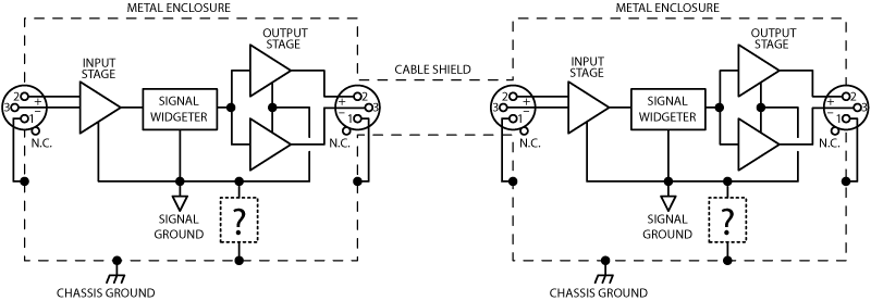
Figure 1. Balanced cable shields should function as an extension of the enclosure.
A Speculative Evolution of Balanced and Unbalanced Systems
One may ask, if the balanced solution is best, why isn't all equipment designed this way? Well, reality takes hold; unbalanced happens.
Back in the early days of telephone and AC power distribution a specific class of engineers evolved. They learned that telephone and AC power lines, due to their inherently long runs, must be balanced to achieve acceptable performance. (To this day, many telephone systems are still balanced and unshielded.) In the 1950s, hi-fi engineers developed systems that did not necessitate long runs, and used unbalanced interconnection. The less expensive nature of unbalanced interconnection also contributed to its use in hi-fi. These two classes of engineers evolved with different mind-sets, one exclusively balanced, the other exclusively unbalanced. The differing design experience of these engineers helped form the familiar balanced and unbalanced audio worlds of today.
Now add spice to the pot with the continued price decrease and praise devoted to balanced, "professional" audio interconnections with the desire for better audio performance at home, and one sees the current trend of merging balanced and unbalanced systems arise. Home studio owners, previously on the unbalanced side of the fence, dream to jump but unfortunately straddle the fence, getting snagged on the fence's ground barbs when connecting their new balanced equipment (Figure 2).
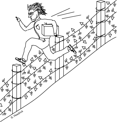
Figure 2. Home studio owner trying to jump the balanced-unbalanced fence.
How Could This Happen?
To fulfill their users' desires to "go" balanced, hi-fi designers started upgrading equipment to balanced. From an unbalanced designer's mind-set, connecting the new balanced circuit's shield to ground is almost subconscious. The issue of which ground connects to the shield is alien or unknown. The old unbalanced "shield" (really the return signal conductor, not a true shield) is already "grounded." Without appropriate balanced interconnection research, this hi-fi mind-set may not think to add a chassis-grounded shield around the existing 2-conductor cable. This redefines the "old" return conductor as a "new" negative signal carrier, not as a shield. It was perhaps the convenience of the situation and this mind-set that started improper signal grounding of balanced shields in the first place. Little treatment of this subject is given in educational institutions, and many systems happen to work satisfactorily even with improperly grounded shields.
Other designers, upgrading to balanced interconnections, may have realized that by connecting the shield to signal ground, interfacing to unbalanced equipment is made simpler since signal ground (needed for unbalanced interconnection) will be available on the cable. (This unfortunately allows easy use of 1/4" mono connectors.) This still creates the same problem, signal-grounded balanced shields. Signal-grounded shields on balanced equipment create ground loops in the audio path and modulate the audio signal ground, wreaking havoc with most systems. This practice penalizes those who want to realize the superior performance of balanced interconnections and has given balancing a bad reputation.
A third possible reason for signal-grounded balanced shields arises if designers change phantom powered microphone inputs to balanced line-level inputs, and do not use caution. The phantom power return currents travel through the shield, requiring shield connection to the signal ground. When changing this topology to line-level balanced inputs, the designer may not think to change the shield connection to chassis ground. This issue is further complicated by manufacturers who incorporate ground-lift switches in their products. These switches disconnect chassis and signal ground. Thus care should be taken to ensure that phantom power return currents always have a return path to their power supply, regardless of the ground-lift switch position.
Manufacturers who started in balanced fields, such as the telephone and broadcast industries, used chassis-grounded shields when maximum protection from electromagnetic interference (EMI, including RF) was necessary. Perhaps users from these balanced fields assumed that all balanced equipment had chassis-grounded shields. When improperly-wired manufacturer's equipment was installed, they discovered hum and buzz problems. They solved them with isolation transformers, by disconnecting one end of the shield, or by simply not using that manufacturer's equipment. The feedback to inform manufacturers of their improper shielding practices never developed. Manufacturers may have suggested isolation transformers or cable rewiring solutions instead of addressing the cause of the problem: signal-grounded balanced shields. Again, some systems with signal-grounded shields work acceptably, causing further and future bewilderment.
The History Lesson
The lesson to be learned from this account involves keeping in mind these audio interconnection issues when specifying, designing, or upgrading other connectivity systems such as AES3 (formerly AES/EBU), SPDIF, and other electrical interfaces. Balanced and unbalanced systems are not designed to interface together directly. As the audio industry embraces more digital products, interconnection systems must be clearly designed and specified for use within the limits of their electrical interfaces. Multiple conductor connectors, carrying either digital or analog signals, present even more challenges. The distance between units is an important issue. Keeping interconnects balanced and chassis-ground-shielded provides the best possible immunity from electromagnetic interference, regardless of cable lengths. Unbalanced interconnection may be less expensive to manufacture and sell, but is perhaps more expensive to install -- hum and buzz-free.
The Audio Engineering Society is to be applauded for assembling and disseminating this information to those who may be unfamiliar with it. Manufacturers and, more importantly, users will eventually be rewarded.
Chassis Ground vs. Signal Ground
Let us examine the distinction between chassis and signal ground in audio devices. Chassis ground is generally considered any conductor which is connected to a unit's metal box or chassis. The term chassis ground may have come about since units with 3-conductor line cords connect the chassis to earth ground when plugged in to a properly wired AC outlet. In units with a 2-conductor line cord (consumer equipment), the chassis does not connect to earth ground, though the chassis is normally connected to the signal ground in the box in both unbalanced/consumer and in balanced/pro equipment.
Signal ground is the internal conductor used as the 0 V reference potential for the internal electronics and is sometimes further split into digital and analog ground sections. Further signal ground splits are also possible, though it is important to remember that all "divisions" of signal ground connect together in one place. This is usually called a star grounding scheme.
It is easy to confuse chassis ground and signal ground since they are usually connected together -- either directly or through one of several passive schemes. Some of these schemes are shown in Figure 3. The key to keeping an audio device immune from external noise sources is knowing where and how to connect signal ground to the chassis.
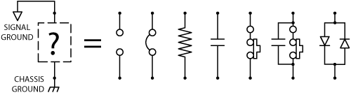
Figure 3. Some passive schemes for connecting signal ground to chassis.
First let's examine why they must be tied together. We'll cover where and how in a moment. There are at least two reasons why one should connect signal ground and chassis ground together in a unit.
One reason is to decrease the effects of coupling electrostatic charge on the chassis and the internal circuitry. External noise sources can induce noise currents and electrostatic charge on a unit's chassis. Noise currents induced into the cable shields also flow through the chassis -- since the shields terminate (or should terminate) on the chassis. Since there is also coupling between the chassis and the internal circuitry, noise on the chassis can couple into the internal audio. This noise coupling can be minimized by connecting the signal ground to the chassis. This allows the entire grounding system to fluctuate with the noise, surprisingly providing a quiet system. Further coupling reduction is gained when the chassis is solidly bonded to a good earth ground -- either through the line cord, through the rack rails or with an independent technical or protective ground conductor. This provides a non-audio return path for any externally induced noise.
The second reason to connect signal ground to chassis is the necessity to keep the signal grounds of two interconnected units at very nearly the same voltage potential. Doing so prevents the loss of system dynamic range where the incoming peak voltage levels exceed the power supply rails of the receiving unit.
Unbalanced units connect successive signal grounds together directly through each interconnecting cable -- the sleeve of each RCA cable. This, and the fact that the chassis is generally used as a signal ground conductor, keeps the signal ground impedance of unbalanced systems very low. Many may agree that unbalanced systems are helped by the fact that the chassis are normally not earth grounded. This allows an entire unbalanced system to float with respect to earth ground. This eliminates the potential for multiple return paths for the audio grounding system, since there is not a second path (ground loop) through the earth ground conductor. Low signal ground impedance between units is essential for acceptable operation of all non-transformer-isolated systems, balanced and unbalanced.
The design of balanced interconnection does not connect signal grounds directly together. The negative conductor provides the required signal return current. To avoid loss of dynamic range, balanced systems use a different method of keeping signal ground potentials small.
Since the cable shield already connects the two chassis together, simply connecting signal ground to the chassis in each box keeps the signal ground potentials between units small. The key is how to connect them. Since the cables between units also provide the shortest (and therefore the lowest impedance) path between two units, using the cable shield to minimize the signal ground potentials between units is quite effective.
Now that we know why one must connect signal ground to chassis, let's discuss how to connect them. The schemes in Figure 3 appear straight forward enough, but what is not shown is precisely where and how the conductors connect together.
It all comes down to paying close attention to where currents flow. As discussed above, the shield noise currents flow through the chassis and shunt to earth ground on units with 3-conductor line cords. The key issue is that these noise currents do not flow through a path shared by any audio currents. It seems so simple, and is -- especially to draw (see Figure 3 again). The hard part is implementing the proper layout scheme.
Connecting signal ground to the chassis in each unit can only be done in one place in each unit. If done twice, one leaves the possibility open that the noise currents will flow through a path shared by audio.
There are two schools of thought on where to connect the signal ground to the chassis. They are both versions of the star ground scheme mentioned above. The first connects a trace (or wire) directly from the audio power supply ground terminal and connects to the chassis ground point (see Figure 4). It is important, in both "schools", that no other signal currents be allowed to flow through this trace. Do not allow this trace to share any other return currents from other signal-grounded circuit points, such as the input or output circuit's ground. This keeps chassis noise currents from flowing through the same trace which is a return path for an audio signal. Also keep in mind that this trace may contain noise currents and should be kept away from noise sensitive circuitry. This is a star grounding scheme which uses a point originating at the output of the power supply as the center of the star. There are two common locations in the power supply for the star's center: the output terminal of the power supply and the point between the AC filter capacitors.
Another school of thought on where to connect signal ground to the chassis simply moves the center of the star ground to the input jack's ground. This scheme makes the most sense for unbalanced units and balanced units equipped with 1/4" connectors where use of mono plugs is possible.
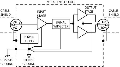
Figure 4. Star ground scheme for connecting signal ground to chassis. Star center may be connected at power supply, or at input ground.
Manufacturer Issues to address
Implementing their users' desires to "upgrade" to balanced, traditionally unbalanced manufacturers are faced with an important issue: How do you solve the balanced/unbalanced incompatibility problem? If you sell your product to a mixed balanced/unbalanced market, a suggested method of interconnection must be available. Isolation transformers and active interface boxes are the best solution and should be offered as the best interconnection alternative. However, persuading unbalanced customers to buy an expensive interface solution is much harder than the lower performance option of rewiring their cables. (The "add-on" transformer solution is analogous to a software company releasing a new software revision which renders your existing files incompatible unless an additional file conversion program is purchased.)
Through careful rewiring of the cables, acceptable interconnection solutions are achievable in some systems. (One of Rane's most popular RaneNotes, Sound System Interconnection, is one example of the "custom" wiring needed in some systems.) This same cable re-wiring solution holds whether the equipment is wired with signal ground or with chassis ground on the balanced circuit's shields.
Solutions for Mixed Balanced and Unbalanced Systems
It is obvious from the vast quantity of literature that for fully balanced operation, the shield should connect to chassis ground at the point of entry. This is also true for unbalanced operation when a third shield conductor is available; connect the shield to chassis ground at the point of entry. However, this is only valid when 2-conductor shielded cable is used.
Shielded 2-Conductor Connectivity
Figure 5 shows recommended wiring for all combinations of balanced and unbalanced I/O interconnections when 2-conductor shielded cable is used. Figure 5 also includes the two most common manufacturer shield-grounding schemes; signal-grounding the shield and chassis-grounding the shield. Identifying these schemes for every unit in a system is essential to debug system hum and buzz. This is no simple task since chassis and signal grounds are connected together. The goal is to find out if the manufacturer connected them together is such a way that shield currents do not affect the audio signal. The dashed lines in Figure 5 represents the units' chassis boundary. Connections between dashed lines are functions of the cable. Connections outside these lines are the manufacturer's choosing, whether conscious or unconscious.
Figure 5 is arranged such that the top and left most figure (5a) is the theoretical "best" way to connect equipment with optimal results. The "best" way being, everything completely balanced with all shields (pin 1s) connected to chassis ground at the point of entry. As one moves down or to the right, degradation in performance is expected. Whether a system operates acceptably or obeys these theoretical predictions is too system-specific to predict accurately. However, one must start somewhere.
The quality and configuration of the input and output circuits are omitted from Figure 5 and the ensuing discussion, to focus on cable wiring and the internal wiring of the units. The I/O circuitry is assumed ideal.
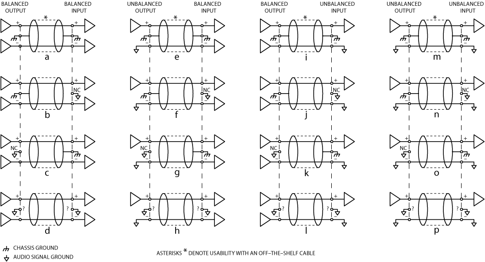
Figure 5. Interconnectivity using shielded 2-conductor cable only. Asterisks denote usability with off-the-shelf cable.
Fully Balanced
Fully balanced systems (left column in Figure 5) provide the best performance when both ends of the shield connect to units with chassis-grounded shields (Figure 5a). When units with signal-grounded shields are encountered, disconnect the shield at the signal-grounded end (Figures 5b & 5c). This keeps the induced shield currents out of the audio signal ground. If both units involved have signal-grounded shields, you have entered the twilight zone (Figure 5d). This is perhaps the most common scheme. Most disconnect one end of the shield, specifically which end is disconnected creates strong political debates and is left for the individual user to decide [6]. Never disconnect both ends of a shield.
Unbalanced Output Driving Balanced Input
The second column in Figure 5 shows unbalanced outputs driving balanced inputs. Again, only shielded 2-conductor cable is used. The best case here has both ends of the shield connected to units whose shield is chassis-grounded (Figure 5e). Some may argue that the induced noise on the signal conductors may be injected into the "sending" unit through the unbalanced output stage. This is a function of the system and output circuit, and is quite likely. Disconnecting the shield at the unbalanced output might reduce this problem.
When units with signal-grounded shields are encountered, disconnect the shield at the signal-grounded end (Figures 5f & 5g). This keeps the noisy shield currents out of the audio signal ground. If both units involved have signal-grounded shields, you've entered the twilight zone again (Figure 5h). Support your one-end-only political party (Figure 5l).
Balanced Output Driving Unbalanced Input
The third column in Figure 5 is the most troublesome, balanced outputs driving unbalanced inputs. Since the input stage is not balanced, induced noise on the signal conductors is not rejected. If you must use an unbalanced input, use as short an input cable as possible. This reduces the induced noise. There's a reason it's hard to find and buy unbalanced RCA cables longer than 12 feet. Figure 5i shows both ends of the cable shield connected to units with chassis-grounded shields. If the units are far apart, the chance of the shield currents inducing noise on the signal conductors is greater. Keeping this cable very short reduces the shield current and therefore reduces the noise that is not rejected by the unbalanced input stage. Most systems may require disconnecting one end of the shield for the Figure 5i case. Even a small current in the shield may prove too much for an unbalanced input stage. Again, support your favorite one-end-only political position.
Disconnect the shield at units with signal-grounded shields (Figures 5j & 5k). If both ends have signal-grounded shields, run for your favorite one-end-only political party. (Figure 5l).
This scheme connects the balanced output's negative output to signal ground, rather than a high impedance input. Many balanced output circuits will attempt to drive this signal ground, causing great distortion and potentially damaging the output stage. Other balanced output stages are termed "floating" balanced. (Analog Devices SSM-2142 Balanced Line Driver chip is one example.) Also called a cross-coupled output, these circuits mimic the performance of fully balanced transformer solutions and are designed so the negative output can short to signal ground. If you find or use this scheme, be sure that the balanced output stage can properly handle signal ground on its negative output.
Full Unbalanced
Fully unbalanced systems do not provide a 3-conductor connector to enable proper use of a shield. In the unlikely event you run across one, use the wiring in the fourth column (Figure 5m-p). Again keeping cable lengths short will reduce noise problems, with or without a shield.
Most home audio systems are fully unbalanced. Millions of these systems work virtually hum and buzz-free every day, due to their small nature, short cable runs and 2-conductor AC line cords. The headaches begin when one tries to add a balanced unit to such a system. In unbalanced home audio products neither of the line cord's conductors connects to the chassis, since plugging older, non-polarized AC plugs into an improperly wired outlet would place the "hot" wire on the unit's chassis. Lack of the third pin on the line cord prevents ground loops in home systems since a second path to ground, or between units, is unavailable. Professional audio equipment generally comes equipped with a 3-wire line cord. The third wire (green wire) is required to connect to the chassis. This provides the second ground path (loop) from one unit to the next.
Connector Choice
Connector type was purposely left out of Figure 5 and the above discussion since connector choice adds another layer of complexity to interconnection systems. The most troublesome culprit is the 1/4" connector. Mono 1/4" connectors are used on most musical instruments and in phone systems. Stereo ¼" connectors are used for headphones, balanced interconnection, effect and insert send/return loops, relay switch closure points, and an extravagant collection of other miscellaneous connections. Murphy's Law tells us, if you provide such a diverse selection of 1/4" interconnection options, they will be hooked up improperly. The audio industry's problem is that many of these options are completely incompatible. A properly wired mono 1/4" connector has signal ground on the sleeve, a properly wired balanced 1/4" connector has chassis ground on the sleeve. Interconnecting this combination should not be achievable -- much like trying to connect 120 VAC to an RCA jack (see Figure 6). The 1/4" connectors low cost, high availability, and small size all contribute to its widespread and varied use. Undoubtedly the numerous interconnection uses of such a popular connector arose for these reasons.
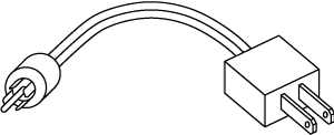
Figure 6. Difficult-to-find connector type.
Sadly, the possibility of including connector type in a recommended practices document is slim. The duplicate connectors on many audio components contributes to higher costs and wastes millions of dollars worth of connectors that are never used. Some manufacturers are attempting to eliminate the 1/4" connector to avoid the confusion and problems when 1/4" jacks are used. This is a step in the right direction, though the high density allowed by these connectors requires less valuable rear-panel real estate. Most marketing departments prefer thirty connectors per inch, making the currently available 3-pin (XLR) alternative markedly unpopular. What is needed is a 3-pin connector solution that requires less space than the traditional XLR connector. A locking, stackable 3-pin mini-DIN comes to mind.
Terminal block and Euroblock connector types are used when separate cable-end connectors are unnecessary or impractical. These connection solutions provide the user with the most wiring options when both signal and chassis ground terminals are available. This allows the user to decide which wiring practice to incorporate. This is the most desirable solution, though most studio equipment does not call for these connector types.
"Hidden" Balanced I/O Solution
An interesting solution for mono interconnection incorporates unshielded balanced stages, much like most telephone systems. Figure 7 shows this configuration. This allows off-the-shelf mono cables to be used to connect unbalanced or unshielded-balanced I/Os to a system. Though not as ideal as a shielded balanced interconnection, systems with mono connectors, like home theatre systems, benefit from this configuration. Keeping cable lengths short is essential and not difficult in a home environment.
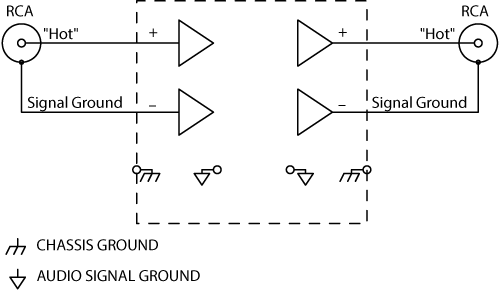
Figure 7. "Hidden" Balanced Interconnection.
One advantage of such a system, besides making it impossible, on fully balanced systems, to get signal ground on an external cable, is that it provides an easy upgrade path to balanced signal connections. The manufacturer need only change the connector to a 3-pin version. Also crucial for this solution is the need to have either cross-coupled output stages or an output that does not mind a grounded negative output, since the negative output may connect to signal ground.
A slight disadvantage lies with the common use of non-twisted pair cables in off-the-shelf mono cables. Using twisted cable with this unshielded balanced scheme greatly improves the achievable performance.
The Muncy Solution
Neil Muncy is an electroacoustic consultant and veteran of years of successful system design. His long standing solution to these issues provides real-world proof of the guaranteed performance achievable with fully balanced systems wired per the Audio Engineering Society recommendation. Mr. Muncy implements what I call the Muncy solution and alters every piece of gear so it has balanced inputs and outputs with both ends of the shield connected to chassis ground at the point of entry. Decades of this practice, and the early research and discipline to understand the basic physics required to implement it properly, have given Mr. Muncy the drive to tirelessly tour the country dispersing his findings. Mr. Muncy's seminars educate those who are ignorant of the "right" way to wire balanced equipment, and show the advantages gained when every piece of gear in the system is wired accordingly.
Current Manufacturer Solutions
Let's examine manufacturer's choices regarding signal-grounding or chassis-grounding balanced cable shields. The problems of signal-grounding balanced shields have already been covered. Users choose to live with hum & buzz, alter off-the-shelf cables by disconnecting one end of the shield or, even in fully balanced systems, use isolation transformers. All are senseless alternatives for inconsistent manufacturing methods. Their advantages and disadvantages are outlined in Tables 1 and 2.
Table 1. Signal-Grounded Balanced Shields |
|
|
Advantages |
Disadvantages |
|
|
Table 2. Chassis-Grounded Balanced Shields |
|
|
Advantages |
Disadvantages |
|
|
For the manufacturer, several shield connectivity choices are available.
- Keep or change shield connections to chassis ground.
Manufacturers who chassis-grounded balanced shields originally must still recommend isolation transformers, cable altering and the technical support that go with these hum and buzz solutions. This is unfortunately necessary, since not all balanced equipment has chassis-grounded shields. Ideally, if all balanced equipment were suddenly and miraculously chassis grounded on both ends at the point of entry, off-the-shelf cables could be used in every system, leaving only the I/O circuitry to dictate system performance. - Change shield connections to signal ground.
Though this would be a step backward, it is still a choice. Most equipment is connected this way and most users have found their own costly "add-on" interconnection solutions. - Offer the shield connection choice to the user.
Provide both options. Two independent screw terminals (one signal, one chassis), a switch or a jumper option permit the user to wire as they please. More on this later.
Manufacturer Solutions for Efficiently and Effectively Connecting Balanced Shields to Chassis
Printed Circuit Board Mounted Jacks
The printed circuit mounted jack provides manufacturers with the most cost-effective solution for transferring cable signals to a printed circuit board. On the board, most manufacturers connect the balanced shield conductor (to signal ground) with a board trace. For optimum balanced performance connect the shield to chassis ground at the point of entry. This means that the shield conductor, to avoid spraying any induced RF energy into the box, never passes the chassis' outer plane. This is not a simple task. Currently no printed circuit mounted 3-conductor connectors provide this optimum solution.
Terminal Strips
When both signal and chassis ground terminals are provided on terminal block or Euroblock connector types, the user decides which wiring practice to incorporate. This is a desirable solution, though a lot of equipment does not call for these connector types. Providing a Pem nut, screw and toothed washer near the cable terminals, instead of an additional chassis-grounded screw terminal, prevents the shield conductor from entering the enclosure -- supplying the ultimate interconnection solution. (This is why Rane terminal strips and Euroblock inputs and outputs have a PEM nut, screw and tooth washer above the shield connection.) Users select their preferred wiring practice, and the shield can not spray RF into the enclosure. Maintaining the shield around the signal conductors all the way to the I/O terminals is important. Keeping the Pem screw near the terminals is therefore essential.
Panel Mount Jacks with Wires
Panel mount jacks require the manufacturer to connect a wire from a terminal pin to the printed circuit board or chassis. This is a good solution for chassis-grounding a shield, though this allows the shield to enter the enclosure. Keep the wire short, the gauge large, and the path to chassis away from sensitive circuits. "Wire" is a four letter word to many manufacturers, and some consider them too costly due to their labor intensive nature. Achieving consistent results with hand-wired connections is difficult, making the PC mounted jack solution more desirable.
L-Bracket or Standoff Solution
A circuit board trace run to a nearby chassis-grounded point is another option. Use of an L-bracket, standoff or similar mechanical connection to the chassis provides mechanical stability, but also consumes valuable rear panel and/or PC board real estate at the same time. Important here is avoiding long traces and keeping the trace away from sensitive areas since it acts as a noise source when shield currents are large or noisy.
Jumper Options
Not as "friendly" as the screw terminal solution, an internal jumper option provides user configuration of internal shield connection points. This allows the use of XLR or 1/4" connectors yet still gives the user control of shield wiring practices. Providing a separate, external switch for this function is not cost effective. Two issues arise with this solution. The first is that there is no external visual indication showing shield connection point. The second issue to address is which position to ship the jumpers in.
The first problem is nothing new. Most manufacturers do not specify where their shields are connected. The unit's manual or schematic, if available, may indicate what ground connects to the shield. The schematic symbols used for grounds are not standardized, though there is an Audio Engineering Society standards group addressing drafting symbols to solve the dangling triangle mystery. Proper schematics indicate which symbols represent signal and chassis grounds. The second issue's answer is clear -- chassis-grounding the balanced shield is the "best" default option, though offering the choice supplies an elegant solution for parties on both sides of the fence. For fully balanced systems, defaulting the shield jumper to chassis provides the best solution, but only when all interconnected units have chassis-grounded shields. Other units with signal-grounded shields short-circuit the shield currents to signal ground when connected, causing potentially nasty modulation of the signal ground. This makes the other guy appear the culprit, but does nothing to solve the problem. Clearly users must be able to determine manufacturer shield wiring practices. Additionally, to support both "one-end-only" shield connection parties, separate input and output jumpers must be provided (see Figure 8).
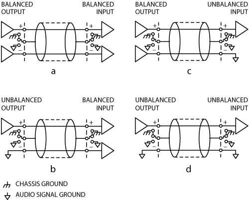
Figure 8. User-Selectable Shield Connections.
Neutrik Solution
Neutrik AG, Liechtenstein, offers snap-in, printed circuit mount jacks with metal brackets which pierce the inside of the chassis when external mounting screws are installed. This chassis-pierced bracket also has a separate pin available through the printed circuit board. The sharp piercing tab provides the electrical connection between the chassis housing and printed circuit board. This solves the problems of the labor intensive wire and the need to connect to a chassis point, providing the best solution for manufacturers and users. [Neutrik's popular "combo" receptacles -- combined female XLR & female 1/4" connectors -- provide this piercing tab feature.] Unfortunately, depending on the available height in a given unit, these jacks have trouble fitting in a single rack space unit due to their slightly larger height. Hopefully other jacks with this built-in feature will become available, providing manufacturers with a cost effective solution to this grounding problem.
Other Suggestions
Many years ago RCA developed their own guidelines for rear panel I/O practices. Some manufacturers and users practice their own methods of left to right interconnection customs. AC and speaker level I/O on one side, microphone and lower level signals on the other side. This permits easier rack wiring and decreases crosstalk between cable runs in the rack and along cable paths. While the recommended practices document may not dictate product design at such a basic level, this type of thinking benefits everyone. With multi-manufacturer standardized network-controlled products popping up everywhere, now is the time to address these basic features. Users with "standardized" interconnection systems, designed with the user in mind by informed engineers, will spend less time debugging and installing systems. This allows more installations per day, generates better, quieter systems and provides more business with smiling users and manufacturers.
Fiber is the Future
Digital fiber optic interconnection solves all the above problems of electrical interconnection systems, though one must face a new set of problems. However, when one adds up the debugging costs of eliminating hum from electrical systems, fiber may not seem as expensive.
Conclusion
Balanced and unbalanced interconnection are two very different beings. The incompatibility between these two configurations, whether using analog or digital signals, must be considered when designing, specifying, installing or upgrading equipment and systems. Literature on the subject of grounding and shielding audio devices dictates chassis-grounding balanced shields. Most manufacturers, however, signal ground their balanced shields. Speculation about how and why this practice materialized was explored. The Audio Engineering Society is developing a recommended practices document which also condones chassis-grounding balanced shields, among other things. It was shown that the manufacturer choice of signal-grounding or chassis-grounding balanced shields does not affect the cable re-wiring and other technical support solutions normally recommended when interconnection of balanced and unbalanced equipment is needed. Therefore manufacturers need not hesitate in addressing their "pin 1 problems," and should provide users with the real benefits of balanced interconnection by providing chassis ground on balanced shields. Efficient and effective ways of doing this were also discussed.
Also covered was the importance of reducing signal ground voltages between interconnected units by carefully and properly connecting chassis ground to signal ground, in one place, in each unit. Vitally important is the manner in which one connects these two grounds together. The same care must be taken when connecting I/O cable shields to the chassis ground. One must avoid common impedance coupling in the shield-to-chassis trace to ensure optimum performance from balanced interconnection.
The goal of the Audio Engineering Society in recommending these balanced interconnection solutions is to reduce or eliminate the need for interconnection work-arounds through education and information sharing. This is the mission statement of the Audio Engineering Society in the first place. Systems installed with chassis-grounded balanced shields on all units, with well-twisted interconnection cables operate hum and buzz-free, leaving only the input and output circuit topology specifications to dictate system performance.
The Audio Engineering Society recommendation's purpose is not to create another "pin 2 is hot" war. In reality, users and installers have found acceptable solutions for "the pin 1 problem" of signal-grounded balanced shields and are unlikely, nor will they be able, to suddenly change over to not using alternatives. Manufacturers specify I/O connector type on data sheets, similarly, we should specify shield connection practices in equipment specifications, on the chassis, or at least in the manual, thus providing users with required information for proper system configuration.
References
- Ott, Henry W., Noise Reduction Techniques in Electronic Systems (John Wiley and Sons, Inc., NY, 1976).
- Morrison, Ralph, Grounding and Shielding Techniques in Instrumentation (John Wiley and Sons, Inc., NY, 1967).
- Morrison, Ralph, Noise and Other Interfering Signals (John Wiley and Sons, Inc., NY, 1992).
- Giddings, Philip, Audio System Design and Installation (Howard W. Sams, 1990).
- Jung, Walt and Garcia, Adolfo, Op Amps in Line-Driver and Receiver Circuits, Part 2, (Analog Dialogue Vol. 27, No. 1, 1993).
- Whitlock, Bill, "System Problems and Equipment Manufacturers" (Systems Contractor News, September 1997).
- Perkins, Cal, Measurement Techniques for Debugging Electronic Systems and Their Interconnection, (Proceedings of the 11th International AES Conference, Portland, OR, May, 1992).
- Sound System Interconnection, (Rane Corporation, Mukilteo, WA, 1985).
- Metzler, Bob, Audio Measurement Handbook, (Audio Precision, Portland, OR, 1993).
A version of this RaneNote was published in the Journal of the Audio Engineering Society, Vol. 43, No. 6, June, 1995.
 "Grounding and Shielding Audio Devices" This note in PDF.
Romanian translation of this RaneNote: P?mîntul ?i de protec?ie dispozitive audio.