 How to Use
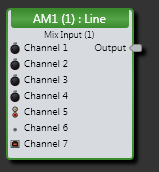
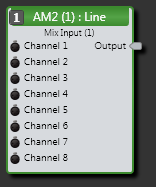
A RAD Mix Input block represents the audio signal received from the output channel of the RAD Automixer (AM1 or AM2) connected to the corresponding RAD port on the HAL or EXP device.
- Click the Processing tab to open the Processing Workspace.
- In the palette area, click the I/O tab.
- In the Remote Audio Device Ports category, find the RAD you want. Click and drag its Mix Input block into your Processing Map.
- Wire the block's output to the appropriate block in the system.
- (Optional) Customize the block name, channel name, and/or output node name by clicking the current name and then typing the custom name in the text box that appears. Click the X to save the name.
note: A RAD does not appear in the I/O palette until it has been added to the system in the Hardware Workspace.
- Open the Mix Input block's properties by double-clicking the block or hovering and clicking the properties icon that appears in the upper right of the block's title bar. From this dialog box, you can do the following:
- Set the volume of the block's output by adjusting the Gain slider or entering a value in the edit box.
- Provide volume control to end users by linking one or more DR1 or DR3 level controls to the block's Level Gain control. You can limit the range of end user volume control by adjusting the minimum and maximum values at either end of the level control. For example, to give the end user 24 dB of attenuation, set the minimum to -24 dB and the maximum to 0 dB. To change these values, click the minimum or maximum value displayed below the slider. An edit box displays in which you can set the Minimum and Maximum parameter values.
- Cause the audio to mute completely when dialed to the low end of its range by selecting the Off @ Min checkbox. Using the example range described above, checking Off @ Min provides continuous volume control from 0 dB to -23.9 dB and then mutes the audio completely.
- Mute the output channel—without changing the specified Gain value—by selecting the block's Mute checkbox. You can provide end users with control over this Mute parameter by linking the block's Mute control to a Logic In, DR2, or DR3 Toggle control.
- View meter data for the audio signal after passing through and after passing through the Level settings.

 See Also