Router
Use the Router block to send an input signal to one of several outputs. Selecting an output channel sends the Router block’s input audio to the specified output channel.
The Router block is useful for assigning wireless mics to different rooms in a room combine.
- Click the Processing tab to open the Processing Workspace.
- In the palette area, click the DSP tab.
- Expand the Selectors category of blocks.
- Click and drag the Router block into your Processing Map.
- Wire it into your system in the appropriate location. If you need additional outputs, simply wire to the <Add> node or click the <Add> text.
- (Optional) Customize the names of the block and/or the output channels by clicking their current name and then typing the custom name in the text box that appears. Click the X to save the name.
- Open the Router block's properties by double-clicking the block or hovering and clicking the properties icon that appears in the upper right of the block's title bar. The properties dialog box displays the list of output channels. From here you can do the following:
- Select a channel (by clicking it) to send the block's input to that channel.
- Provide end user control over the channel routing by linking the Router selector control to a DR2 or DR3 selector control. When active in a link, the Router properties include the display names for the output channels next to the block's channel names.
note: A DR selector is limited to a maximum of 20 selections. This means that to link a DR selector to a router block, the total number of outputs must be 20 or less and when linked, the router block can have a maximum of 20 outputs.
| UI Element | Purpose |
|---|---|
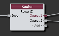
| Input node | Connection point for wiring input to the Router block. |
| Output nodes |
Connection points for wiring the Router input to specific outputs. Current selection is indicated on the block by coloring the corresponding node and output name. |
| <Add> node | Click to add another Output node, or wire to the <Add> node to automatically create a new channel. |
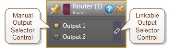
(Hover over the thumbnail below to view the properties dialog box.)
| UI Element | Purpose |
|---|---|
| Selector Control | Click a radio button to select the output to which the Router will send its input. Provide end users with output selection control by linking this Selector Control to the Selector Control of a DR2 or DR3. |
 See Also