Priority Selector
Use the Priority Selector block to manually choose one of several possible audio signals or to automatically select a priority input when audio is detected on that input. Selecting an input channel (manually or automatically) sends that channel’s audio to the Priority Selector block’s output.
The Priority Selector block has two signal detectors (priority 1 and priority 2) and a manual source selector. If no audio is detected by the priority detectors, the source selected by the manual selector is routed to the block's output. If a priority signal exceeds the Threshold (set in the block's Detector Settings), that detector becomes active, its audio is routed to the block’s output, and the audio of lower priority inputs is muted and no longer routed to the block’s output. When the priority signal drops below the detector Threshold, the detector remains active for the Hold Time. If the priority audio exceeds the Threshold before the Hold Time expires, the priority audio continues uninterrupted to the output. If the Hold Time expires, the lower priority input is routed to the block's output. The lower priority output is also unmuted and its volume ramps back up to normal over the time specified in the block's Ramp Back setting.
The Priority Selector Block is useful for allowing audio input from a priority source to override the selection made by an end user. One example is a restaurant with background music, a TV, and a jukebox. When the TV is on, its audio should override the background music. When the jukebox is playing, its audio should override the TV and background music (since someone paid a quarter for that song). In this situation, three inputs are wired to the priority selector (BGM, TV, and JUKE). The Priority 1 detector is set to JUKE, the Priority 2 detector is set to TV, and the manual selector is set to BGM. Optionally, a DR2 or DR3 selector could be linked to the manual selector, allowing the restaurant staff to leave the source set to TV or JUKE by default.
- Click the Processing tab to open the Processing Workspace.
- In the palette area, click the DSP tab.
- Expand the Selectors category of blocks.
- Click and drag the Priority Selector block into your Processing Map.
- Wire it into your system in the appropriate location. If you need additional inputs, simply wire to the <Add> node or click the <Add> text.
- (Optional) Customize the name of the block and/or its Input node(s) and Output node by clicking the current name and then typing a custom name in the text box that appears. Click the X to save the name.
- Open the Priority Selector block's properties by double-clicking the block or hovering and clicking the properties icon that appears in the upper right of the block's title bar. From here you can do the following:
- Manually select an input channel by clicking it in the manual selector at the bottom of the block, which then sends that input to the block's output.
- Provide end user control over the manual input selection by linking the block's selector control to a DR2 or DR3 selector control. When active in a link, the display names for the input channels appear next to the block's input channel names.
-
note: A DR selector is limited to a maximum of 20 selections. This means that to link a DR selector to a priority selector block, the total number of inputs must be 20 or less and when linked, the priority selector block can have a maximum of 20 inputs.
- Select one or two Priority Inputs (in the area above the selector list). Associated with each priority input is an indicator that lights yellow when that audio exceeds the detector's Threshold (indicating that the priority channel is now being routed to the block’s output).
- Expand and configure the Priority Selector block's Detector Settings. These parameters are shared by the priority detectors.
- Set the Threshold above the noise floor of priority inputs and below the softest signal you want to detect. A higher Threshold makes the detector more immune to noise but also requires hotter input audio to activate the detector.
- The Low-cut and High-cut filters allow you to band-limit the audio monitored by the detector, allowing the detector to ignore signals that may unintentionally activate the detector in some installations (for example hum, hiss, rumble, and so on). Increase the reliability of the detector by matching the detector’s bandwidth to the bandwidth of the signals you are trying to detect (rejecting out-of-band noise).
- Adjust the Hold Time to slightly longer than the longest gap you expect in your priority audio signal. For example, if the priority input is a jukebox, the Hold Time should account for the time it takes the jukebox to change CDs and begin playing a new song. If the Hold Time is too short, the lower priority audio (for example, background music) may begin playing between songs.
- Use the Ramp Back time to set the rate at which the lower priority audio returns to normal volume. In our jukebox example, Ramp Back specifies the time it would take to bring the background music back to its normal listening level. Note that an instantaneous Ramp Back may be too abrupt—dropping right into the middle of a song at full volume.
| UI Element | Purpose |
|---|---|
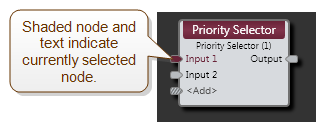
| Input nodes |
Connection points for wiring inputs to the Priority Selector block. Current selection is indicated on the block by coloring the corresponding node and input name. |
| Output node | Connection point for wiring the Priority Selector input to an output. |
| <Add> node | Click to add another Input node, or wire to the <Add> node to automatically create a new channel. |
(Hover over the thumbnail below to view the properties dialog box.)

| UI Element | Purpose |
|---|---|
| Priority Inputs | Specifies one or two inputs that take precedence over other inputs. When the signal from a priority input exceeds the Threshold (see below), that input becomes active, its associated indicator lights yellow, its audio is routed to the block’s output, and the audio of lower priority inputs is muted and no longer routed to the block’s output (until the priority input's signal falls below the Threshold). |
| Selector Control | Click a radio button to select the input to be routed to the block's output. Provide end users with input selection control by linking this Selector Control to the Selector Control of a DR2 or DR3. |
| Threshold |
The signal level that must be detected from a priority input for it to become active. Default = -60 dBFS |
| Low-cut and High-cut |
Filters that allow you to band-limit the audio monitored by the detector, allowing the detector to ignore signals that may unintentionally activate the detector in some installations (for example hum, hiss, rumble, and so on). Increase the reliability of the detector by matching the detector’s bandwidth to the bandwidth of the signals you are trying to detect (rejecting out-of-band noise). Low-cut default = 40 Hz; High-cut default = 4000 Hz |
| Hold Time |
When the priority signal drops below the detector Threshold, the detector remains active for the Hold Time. Adjust the Hold Time to slightly longer than the longest gap you expect in your priority audio signal. Default = 3 seconds |
| Ramp Back |
The rate at which the lower priority audio returns to its normal volume (after the priority input's signal drops below the Threshold and its Hold Time expires). Default = 3 seconds |
 See Also