You are here: Reference for Processing Blocks and Controls > I/O Processing Blocks > Remote Audio Devices > Mic/Line/Line-Plus Input
Mic/Line-Plus Input
How to Use
An analog Mic/Line-Plus Input block represents the input audio connected to the corresponding analog input port on a RAD16z. These universal inputs can be configured for a Dynamic Mic, Condenser Mic with +24 V phantom power, Unbalanced L & R mono, or Balanced line-level.
Adding the Block to Your System
- Click the Processing tab to open the Processing Workspace.
- In the palette area, click the I/O tab.
- In the palette, scroll down to find the RAD device you want, then click and drag the Mic/Line-Plus Input channel block that you want to use into your Processing Map.
- (Optional) Customize the block name, channel name, and/or output name by clicking the current name and then typing the custom name in the text box that appears. Click the X to save the name.
Configuring the Block
Open the Mic/Line-Plus Input block's properties by double-clicking the block or hovering and clicking the properties icon that appears in the upper right of the block's title bar.
- Designate if the input is Dynamic Mic, Condenser Mic with +24 V phantom power, Unbalanced L & R mono, or Balanced line-level by selecting the corresponding radio button (in the Sensitivity area).
- Also in the Sensitivity area, adjust the Gain to the appropriate level depending on the sensitivity of the microphone or input source in use.
- In the Level area, set the volume of the block's output by adjusting the Gain slider or entering a value in the edit box.
- Provide volume control to end users by linking one or more DR1, DR3, DR6, Web Control, or Ethernet control system level controls to the block's Level Gain control. You can limit the range of end user volume control by adjusting the minimum and maximum values at either end of the level control. For example, to give the end user 24 dB of attenuation, set the minimum to -24 dB and the maximum to 0 dB. To change these values, click the minimum or maximum value displayed below the slider. An edit box displays in which you can set the Minimum and Maximum parameter values.
- Cause the audio to mute completely when dialed to the low end of its range by selecting the Off @ Min checkbox. Using the example range described above, checking Off @ Min provides continuous volume control from 0 dB to -23.9 dB and then mutes the audio completely.
- Mute the input channel—without changing the specified Gain value—by selecting the block's Mute checkbox. You can provide end users with control over this Mute parameter by linking the block's Mute control to a Logic In, DR2, DR3, or DR6 Toggle control.
- View meter data (when connected to a HAL) for the block's audio signal after passing through the Sensitivity settings and also after passing through the Level settings.
User Interface Elements
Mic/Line/Line-Plus Input Block
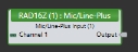
| UI Element | Purpose |
|---|---|
| Analog Input (Channel 1) | Name identifying the incoming analog input channel in the RAD device. You can edit this name by clicking it and then typing the new name in the edit box that appears. |
| Output node | Connection point for wiring the Mic/Line/Line-Plus input channel to another block's input |
Mic/Line/Line-Plus Input Block Properties
| UI Element | Purpose |
|---|---|
| Input Type |
Input Type sets the mode of operation for the two universal analog inputs.
|
| Gain(Sensitivity) | Use the digital Gain control to trim the input gain (sensitivity) appropriately for the source being used. Gain is usually set so that a typical input signal indicates between 0 and 4 dBr on the meter. The range of the Gain control is always 20 dB. Phantom power and the minimum analog gain settings are automatically set for each input type. For example: Dynamic Mic has a minimum analog gain of 26 dB, Condenser Mic has a minimum analog gain of 14 dB with phantom power, Line-Plus and Balanced Line are unity gain. |
| Level block |
|
 See Also