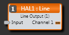
Line Output Block
An analog Line Output block represents the audio sent from the corresponding analog output port on HAL.
- Click the Processing tab to open the Processing Workspace.
- In the palette area, click the I/O tab.
- In the Analog Output Ports category, click and drag the appropriate Line Output block into your Processing Map.
- Wire the appropriate input from your system to the block's Input node.
- (Optional) Customize the block name, input node, and/or output channel name by clicking their current name and then typing the custom name in the text box that appears. Click the X to save the name.
- Open the analog Line Output block's properties by double-clicking the block or hovering and clicking the properties icon that appears in the upper right of the block's title bar. From this dialog box, you can do the following:
- Set the volume of the block's output by adjusting the Gain slider or entering a value in the edit box.
- Provide volume control to end users by linking one or more DR1 or DR3 level controls to the block's Level Gain control. You can limit the range of end user volume control by adjusting the minimum and maximum values at either end of the level control. For example, to give the end user 24 dB of attenuation, set the minimum to -24 dB and the maximum to 0 dB. To change these values, click the minimum or maximum value displayed below the slider. An edit box displays in which you can set the Minimum and Maximum parameter values.
- Cause the audio to mute completely when dialed to the low end of its range by selecting the Off @ Min checkbox. Using the example range described above, checking Off @ Min provides continuous volume control from 0 dB to -23.9 dB and then mutes the audio completely.
-
Invert signal polarity to correct wiring errors implemented by accident or on purpose by unsuspecting installers or uninformed manufacturers. We still recommend fixing such wiring errors when they’re encountered, so future generations will look back on your installation as the ultimate example of truth, justice and proper polarity.
- Mute the output channel—without changing the specified Gain value—by selecting the block's Mute checkbox. You can provide end users with control over this Mute parameter by linking the block's Mute control to a Logic In, DR2, or DR3 Toggle control.
- View meter data for the output signal.
| UI Element | Purpose |
|---|---|
| Input node | Connection point for wiring the input to the Line Output block |
| Analog Output (Channel 1) | The output channel connected to the corresponding analog output port on the HAL |

| UI Element | Purpose |
|---|---|
|
Gain (Linkable Control) |
Gain (a linkable control) sets the volume of the block's output. Also specified is the volume range with a Minimum and Maximum value. Change the volume by adjusting the slider or entering a dB value in the edit box. Provide end users with control over the volume by linking this Level Control to the Level Control of a DR1 or DR3. Change the range by clicking the Minimum or Maximum value and then typing new values in the edit box that appears. The meter displays signal data for the block output. Default Gain = 0.0 dB; Default Minimum = -88.0; Default Maximum = 12.0 |
| Off @ Min Checkbox | When checked, causes the audio to mute completely when dialed to the low end of its range. |
| Invert | When checked, inverts the signal polarity. |
| Mute (Manual and Linkable Control) | Mute the block's output without changing the Gain value. Provide end users with output mute control by linking this Toggle Control to the Toggle Control of a DR2, DR3, or Logic In port. |
 See Also