Cut Filter
The Cut block contains one high-cut and one low-cut filter. High-cut and Low-cut filters remove (cut out) frequencies above or below their frequency setting, thereby limiting the upper or lower frequency range. Audio systems typically do not require true 20 Hz to 20,000 Hz frequency response. For example, typical speech has a frequency range of 200 Hz to 4 kHz. Cutting frequencies below 200 Hz eliminates low frequency noise picked up by microphones (HVAC systems, thumps, etc) and helps tame plosives in speech. Cutting frequencies above 4 kHz helps remove unwanted high frequency noise, such as white noise from fans and fountains.
- Click the Processing tab to open the Processing Workspace.
- In the palette area, click the DSP tab.
- Expand the Filters category of blocks.
- Click and drag the Cut block into your Processing Map.
- Wire it into your system in the appropriate location.
- (Optional) Customize the names of the block and the input and output node by clicking their current name and then typing the custom name in the text box that appears. Click the X to save the name.
- Open the Cut block's properties by double-clicking the block or hovering and clicking the properties icon that appears in the upper right of the block's title bar. From here, you can do the following:
- Select a filter. The Cut block contains one Low-cut and one High-cut filter. To select a filter, you can either click its frequency handle in the graph or select it in the table view (at the bottom of the properties dialog box).
- After selecting a filter, use the Frequency, Type and Slope/Order (alignment), and Bypass controls to configure the frequency response of the filter.
- You can use the brown frequency handles on the graph to control a filter's frequency at any time.
- You can bypass either filter by selecting its Bypass checkbox. Bypassing a filter effectively turns that filter into a wire.
note: A bypassed filter’s magnitude/phase response and frequency handle are hidden in the graph. By default the graph only displays the composite magnitude response (the total result of every filter in the block).
- To view the individual contribution of a selected filter, check the Individual button in the View box in the upper right corner of the dialog box. You can also display the individual and composite phase response by checking the Phase checkbox.
| UI Element | Purpose |
|---|---|
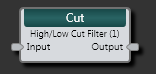
| Input node | Connection point for wiring input to the Cut filter block |
| Output node | Connection point for wiring the Cut filter output to another block |
(Hover over the thumbnail below to view the properties dialog box.)

| UI Element | Purpose |
|---|---|
|
Response graph |
Graphical representation of filters. Shows Magnitude vs. Frequency by default. Use the brown handles to adjust a filter's frequency. Use View options to change graph content. |
| View options | Selecting Magnitude (selected by default) displays the filters' Magnitude on the graph. Selecting Phase (deselected by default) displays the filters' phase response on the graph. Selecting Composite (selected by default) displays frequency handles for both filters on the graph. Selecting Individual (deselected by default) displays the individual contribution of the selected filter. |
| Frequency control | Displays the current corner frequency of the selected filter. Change the frequency by moving the slider or editing the frequency value in the edit box. |
| Type and Slope/Order | Displays the Type and Slope/Order (alignment) associated with the selected filter. To select a different option, click the down arrow and choose from the list that appears. |
| Bypass (above Table View) | Selecting this checkbox bypasses the selected filter, which effectively turns the filter into a wire. |
| Filter Table View | Displays the Frequency, Type, and Slope/Order for each filter. To select a filter, click its row in the table. You can also bypass a filter by selecting its associated Bypass checkbox. |
| Bypass All | Selecting this checkbox bypasses both filters. |
 See Also