Crossover: 2-way mono Filter
The Crossover block uses a combination of high-pass, low-pass, and band-pass filters to divide the audio frequency spectrum (20 Hz to 20,000 Hz) into distinct segments, or ranges, suitable for individual loudspeaker use. All-pass filters built into the Crossover block automatically phase compensate the outputs at the crossover points.
- Click the Processing tab to open the Processing Workspace.
- In the palette area, click the DSP tab.
- Expand the Filters category of blocks.
- Click and drag the appropriate Crossover block into your Processing Map. Mono and stereo versions of 2, 3, and 4-way Crossover blocks are available.
- Wire it into your system in the appropriate location.
- (Optional) Customize the names of the block and the input node and High/Low output nodes by clicking their current name and then typing the custom name in the text box that appears. Click the X to save the name.
- Open the Crossover block's properties by double-clicking the block or hovering and clicking the properties icon that appears in the upper right of the block's title bar. The graph in the properties dialog box displays the current filter curves. From here, you can do the following:
- Choose to work in Simple Mode (the default) or switch to Advanced Mode by clicking the To Advanced Mode button located just below the lower right corner of the graph.
- In Simple Mode, the frequency controls between pass-bands are linked, and all filters use the same Type/Order (alignment). When the crossover frequencies of adjacent bands and all alignments are equal, the crossover block’s internal all-pass filters are able to automatically phase compensate the outputs (for all filter alignments except 1st-order). When the outputs are phase compensated, the dialog box displays Phase Compensated just below the graph.
- Advanced mode allows you to independently set the cut-off frequencies and alignments (Type and Slope) of each band-pass filter. To get back to Simple Mode click the button (which now displays To Simple Mode) again.
- Change the crossover frequencies by clicking and dragging the brown handle at each crossover point or by editing the crossover filter's Frequency and/or Type and Slope/Order in the middle of the dialog box. There are three ways to select a specific filter: Click its brown handle in the graph, select it from the dropdown list located just below the lower left corner of the graph, or select it in the Table View located at the bottom of the dialog box (click Show Table View to display the table). Once selected, all controls for the selected frequency band are displayed across the center of the dialog.
- Adjusting the Frequency sets the crossover frequency between adjacent bands (Simple Mode).
- The Type and Slope/Order control selects the alignment of all crossover filters (Simple Mode).
- Due to variation in amplifiers and loudspeaker efficiencies, each output band may require a slightly different output level. Use the Gain control on each band to set the relative levels of Crossover block outputs.
Add Delay to the output. The physical construction of multi-way loudspeaker cabinets often results in drivers being offset by some distance. This displacement means that audio at the crossover frequencies, being driven from adjacent but offset drivers, acoustically sum out of phase. Adding Delay to the output of the driver closer to the audience gives the audio from the further driver a chance to catch up, eliminating acoustic phase interference at the crossover frequencies. Sound travels approximately 13.5 inches per millisecond. So, the maximum output delay of 10 milliseconds could compensate for drivers that are as much as 11 feet apart.
- Mute each output of the Crossover block independently while you characterize the frequency response of other drivers in the loudspeaker.
- Invert the output of any band to compensate for reversed wiring on an amplifier or loudspeaker channel.
- Choose to work in Simple Mode (the default) or switch to Advanced Mode by clicking the To Advanced Mode button located just below the lower right corner of the graph.
| UI Element | Purpose |
|---|---|
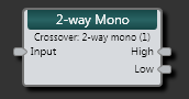
| Input node | Connection point for wiring input to the 2-way Mono Crossover block |
| High node | Connection point for wiring the block's High output to another block |
| Low node | Connection point for wiring the block's Low output to another block |
(Hover over the thumbnail below to view the properties dialog box.)

| UI Element | Purpose |
|---|---|
|
Response graph |
Graphical representation of filters. Use the brown handle to adjust the selected filter's frequency. |
| Filter selection list | Select the filter to display and configure. |
| Mode button | Displays the current configuration mode. The default mode is Simple, in which the frequency controls between pass-bands are linked, and all filters use the same Type/Order (alignment). Advanced mode allows you to independently set the cut-off frequencies and alignments (Type and Slope) of each band-pass filter. To change the mode, click this button. |
| Frequency control | Displays the current frequency of the selected filter. Change the frequency by moving the slider or editing the frequency value in the edit box. |
| Type and Slope/Order control | Displays the Type and Slope/Order (alignment) associated with the selected filter. To select a different option, click the down arrow and choose from the list that appears. |
| Gain control | Set the relative levels of the Crossover block's outputs. |
| Delay control | Add Delay to an output to eliminate acoustic phase interference at the crossover frequencies (in situations where the drivers in multi-way loudspeaker cabinets are offset by some distance). |
| Invert | Compensate for reversed wiring on an amplifier or loudspeaker channel by checking this box to invert the output of any band. |
| Mute control (beneath Invert) | Check this box to mute each output of the Crossover block independently while you characterize the frequency response of other drivers in the loudspeaker. |
| Table View | Displays the settings for each filter. You can also mute an output by selecting its associated Mute checkbox. |
| Mute All | Selecting this checkbox mutes all outputs. |
 See Also