Ducker
The Ducker is a form of dynamics processing and talkover mixer that reduces the main input signal by a predetermined amount when the side-chain level exceeds a threshold. It is also possible to trigger the ducker using a push-to-talk (duck) button rather than a side-chain signal. When used, the side-chain input is always a different signal from the input signal. The user may elect to mix the side-chain input with the main input to form a complete ducker circuit.
Common uses of the ducker are reducing background music levels during a page, giving priority to one microphone over another microphone or signal, and reducing normal program levels during an emergency message broadcast.
note: If you have multiple sources and/or multiple zones requiring ducking and/or paging, or you need more than two levels of ducking priority, take a look at Halogen's advanced paging, zone processing, gain-share automixers, and room combine blocks. Each of these blocks perform this function and are often superior solutions, saving you a great deal of time and effort during the design process. If you have very few signals to duck, the standalone Ducker block is a great choice.
Adjustable side-chain 2nd-order Butterworth high- and low-cut filters limit the detector response to only frequencies of interest and permit lower threshold settings while avoiding unwanted triggering from out-of-band signals. Four times over-sampled true peak detection in the side-chain reduces detection errors. A short sixteen sample, 0.3 ms, look-ahead delay in the side-chain mix path creates a pre-ramp that avoids clicking and ensures that the input ducks before the triggering signal is heard in the mix. A hold time function prevents the Ducker from turning off during pauses in the side-chain signal.
For additional information on Ducker functionality, take a look at the following RaneNotes:
- Click the Processing tab to open the Processing Workspace.
- In the palette area, click the DSP tab.
- Expand the Dynamics category of blocks.
- Click and drag the Ducker block into your Processing Map.
- Wire it into your system in the appropriate location.
-
note: Unlike the AGC and Compressor, the Ducker's main input is not automatically connected to the side-chain input; you must either connect the Side-chain input or use a Toggle Control Link to engage the Ducker, using an external contact closure for example. You can link the Force Duck checkbox to either a Logic input (switch closure) and/or to the relay output to inform another logic input device that ducking has occurred.
- (Optional) Customize the names of the block and the input and output node by clicking their current name and then typing the custom name in the text box that appears. Click the X to save the name.
tip: It is best to place a Ducker so that user level controls cannot alter the signal level driving the side-chain as gain changes would severely hamper the intended operation.
- Open the Ducker block's properties by double-clicking the block or hovering and clicking the properties icon that appears in the upper right of the block's title bar. From here, do the following:
- Set the pass-band of the Side-chain Control. The designer normally sets the initial value at design time with tweaking on site. The setting of the Low-cut and High-cut Filters depends on the intended side-chain source and can range from about 200 Hz to 3 kHz for speech and 80 to 8 kHz for music. When the side-chain source is a microphone, further adjustment may be necessary after installation to prevent unwanted noise caused by machinery or background noise from triggering the ducker.
- Set the Threshold to maximum and create the desired link to the Force Duck switch for push-to-talk applications. Push-to-talk is preferred when possible because varying noise at the main input forces both undesired ducking and installer baldness (due to the pulling out of hair from inconsistent ducking).
- For most applications, it is best to set the Attack for the fastest response. Doing so ensures that the input ducks quickly—before the side-chain signal is mixed (when using the Side-chain Talkover feature). Note that look-ahead delay and pre-ramping enable very quick response without artifacts.
For automatic ducking, you must set the Threshold properly. First, make sure the gain of the source driving the side-chain is set correctly and will not be changing, and then set the Threshold. For microphone sources, set the Threshold such that a soft talker triggers the Ducker. For recorded messages or music, set the Threshold just above the noise floor. A lower Threshold setting operates the Ducker sooner, while a higher Threshold setting is more noise immune.
The Release time determines how quickly the input volume turns back up after the side-chain signal drops below the Threshold or the push-to-talk switch is released. The Release setting varies with application, but the goal is generally to turn the level up at a rate that sounds comfortable and does not surprise listeners.
The length of the Hold Time varies with application. It should be set so that anticipated pauses in speech or other program material do not cause the Ducker to release before the entire announcement is completed.
| UI Element | Purpose |
|---|---|
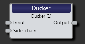
| Input node | Connection point for wiring input to the Ducker block |
| Side-chain node |
The Ducker’s detector is fed from a side-chain input node, providing the signal used to trigger the Ducker when no push-to-talk or other logic forces ducking. An over-sampled true peak signal detector is used. Adjustable side-chain filters permit applications that benefit from band-limited detection. |
| Output node | Connection point for wiring the ducked input signal to another block |

| UI Element | Purpose |
|---|---|
| Response graph/meter | Graphical representation of signal with Duck indicator. Use the green handles to coarsely adjust Threshold and Depth. A real-time side-chain meter shows the Ducker Depth relative to Threshold. |
| Threshold |
The Threshold control determines the side-chain input level above which the input ducks. The graph displays side-chain input in dBFS on the x-axis and output level on the y-axis for any side-chain input level between 0 dBFS and -100 dBFS. The Threshold is the point at which additional side-chain input ducks the output level. There are four controls for adjusting the Threshold: a spin button, text entry, rotary knob, and clicking the green square to drag the Threshold along the x-axis. |
| Depth | Determines how much attenuation in dB to apply to the main input signal when the side-chain level goes above the Threshold. There are four controls for adjusting the depth; a spin button, text entry, rotary knob and clicking on the green graphic to drag the depth along the y-axis. |
| Attack | Determines how fast the Ducker turns down the input signal. The set value describes how long it takes a step to settle to within 95% of the final value. Three controls are available for adjusting the attack time: a spin button, text entry and rotary knob. Because the range of allowed attack time covers several decades, this parameter uses a log response with equal weight given to each decade. |
| Release | Determines how fast the ducked signal returns to unity gain. The value describes the time required for a 10 dB step to settle to within 95% of the final value. Three controls are available for adjusting the release time constant: a spin button, text entry and rotary knob. Because the range of allowed release time covers several decades, this parameter uses a log response with equal weight given to each decade. |
| Hold Time | Determines how long to continue ducking the main input when the side-chain level drops below the Threshold or the Duck switch releases. Use of this parameter prevents un-ducking of the main input when pauses in speech or music occur. Three controls are available for adjusting the hold time: a spin button, text entry and rotary knob. |
| Low-cut Filter | The 2nd-order Butterworth Low-cut filter sets the lower pass-band for the side-chain. Three controls adjust the filter cut-off frequency: a spin button, text entry and rotary knob. This parameter adjusts the frequency in one Hertz steps. |
| High-cut Filter | The 2nd-order Butterworth High-cut filter sets the upper pass-band for the side-chain. Three controls adjust the filter cut-off frequency: a spin button, text entry and rotary knob. This parameter adjusts the frequency in one Hertz steps. |
| Force Duck | Checking the Force Duck box causes the Ducker to operate regardless of side-chain input level. Use it to test Ducker operation or for troubleshooting. Force Duck links to external controls. Use it to provide either push-to-talk operation from an external switch to enable ducking, and/or send Duck active/inactive indication to external logic using a HAL relay output. Force Duck is a Toggle Control Link. The push-to-talk physical switch is usually momentary as using a latched switch results in persistent Ducker operation—which may be desired in some applications. When linked to an external logic input (a read-only switch), Force Duck is disabled in software requiring the physical switch to be used to toggle ducking. |
| Side-chain Talkover | Checking this box mixes a very slightly delayed (0.3 ms) version of the side-chain input with the main input allowing the side chain to be heard. |
| Bypass |
Checking the Bypass checkbox turns the Ducker block into a straight-through wire, although the side-chain meter continues to function. Yellow bars in the Processing Map indicate a bypass. |
 See Also