Compressor
A Compressor is a signal processing device used to reduce the dynamic range of the signal passing through it. The Compressor block allows you to set a threshold point above which everything turns down an amount determined by the ratio setting. Simple, right? Well, it's not quite as easy as it sounds as there are other issues to consider. See How to Use below for more details.
note: Compressor settings can vary substantially depending on the application. It would be impossible in this Help System to cover the detailed solutions for a wide variety of applications. There are, however, additional resources available (RaneNotes) that provide some classic settings for various applications: Detailed definition of a compressor, Compressor and Peak Limiter Applications (see Chapter 8 in the RaneNote), and Signal Processing Fundamentals
- Click the Processing tab to open the Processing Workspace.
- In the palette area, click the DSP tab.
- Expand the Dynamics category of blocks.
- Click and drag the Compressor block into your Processing Map.
- Wire it into your system in the appropriate location.
tip: It is beneficial to place compressors close to the source in order to maximize the dynamic range of downstream signal processing. Placing a compressor after equalization can cause serious artifacts due to unwanted changes in sensitivity over the audio spectrum—yet this may be exactly what you want for a few specific applications such as de-essing.
- Open the Compressor block's properties by double-clicking the block or hovering and clicking the properties icon that appears in the upper right of the block's title bar. From here you can do the following:
- Select a Threshold and Ratio that provide the desired dynamic range reduction. A ratio of 2:1 or 3:1 is generally a good starting point for most situations and should not get you into too much trouble!
- Select a Knee value. A Knee of 5 dB is adequate to reduce distortion at the Threshold.
- Set the Attack and Release values. Moderate amounts of dynamic range gain reduction (a few dB) can use an attack time of 25 to 100 ms with a long release time about five times the attack time. With moderate compression, makeup gain is generally not required. High levels of dynamic range gain reduction (8 to 12 dB and beyond) work best with an attack time of 10 to 50 ms and a release time of at least ten times the attack time.
- Decide whether or not to use Auto Mode. With both moderate and high gain reduction, Auto Mode allows a wider range of attack and release settings without causing unwanted artifacts.
- Set the output makeup Gain. When a lot of dynamic range reduction is required, output makeup Gain is also required to restore the output level. The output meter is a good tool for setting the optimum headroom at the output.
tip: Keep in mind that the basic idea of a compressor is to reduce the dynamic range of a signal so that it fits a particular listening-environment or recording medium. The best approach to this calibration is a combination of using the graph, viewing the side-chain meter, and listening. Using all three functions gives the user an excellent understanding of what the compressor is doing.
| UI Element | Purpose |
|---|---|
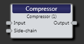
| Input node | Connection point for wiring input to the Compressor block |
| Side-chain node |
The side-chain detects the incoming signal level and calculates the correct gain to apply to the input signal. The side-chain has a separate input, allowing external processing when desired. When not externally wired, the side-chain connects internally to the main input. |
| Output node | Connection point for wiring output from the Compressor block to another block |

| UI Element | Purpose |
|---|---|
| Response graph/meter | Graphical representation of the signal. Use the green handles to coarsely adjust Threshold and Ratio. A real-time side-chain meter shows the gain reduction relative to Threshold. The meter accurately follows the attack and release rate of compression. |
| Threshold |
Represents the side-chain level in dBFS above which signals are compressed. |
| Ratio | When the main input signal exceeds the Threshold setting, the volume change depends on the Ratio setting. The Ratio tells the Compressor how much to turn the output volume down for a given increase in input level above the Threshold. For example, with the Ratio set to 2 (representing a 2:1 ratio), for every 2 dB increase in input signal the output signal only increases by 1 dB. |
| Knee | Controls the action at the Threshold point. Hard Knee does nothing until the signal exceeds the Threshold point, and then applies compression according to the Ratio setting. Use of a soft Knee significantly reduces distortion caused by abrupt transitions from unity gain to a compressed signal. The center of the Knee is located exactly at the Threshold with a smooth transition from unity gain to the specified ratio. |
| Attack | Defines how quickly the Compressor responds to a stepped increase in Side-chain Input level above the Threshold. For compressors, this parameter defines how quickly the Gain turns down. Because increasing time has a diminishing effect on Gain reduction, the Attack parameter represents the time it takes for Gain to settle to 95% of the final value. |
| Release | Defines how quickly the Compressor responds to a stepped decrease in Side-chain Input level above the Threshold. For compressors, this parameter defines how quickly Gain reduction decreases. The Release parameter represents the time required for a 10 dB change. |
| Auto Mode | Compressor designs must contend with a trade-off between fast attack and release response, and low frequency distortion resulting from ripple in the side-chain detector modulating the input signal in the gain control element. Longer release times reduce distortion while faster release times improve response. Use of an adaptive release time, based on side-chain history, makes this trade-off unnecessary by increasing the release time for slow moving signals and reducing the release time for fast moving signals. Auto Mode enables the adaptive release time function and is almost good enough to solve the world peace problem—so, unless you’re an advanced compressor user, we highly recommend using Auto Mode! |
| Output Gain and Meter | Providing ±12 dB of Output Gain adjustment allows the system designer to modify the amplitude of the signal without having to alter Compressor settings. Sometimes it is desirable to apply significant compression over a wide dynamic range. While this approach has the desired effect of reducing the dynamic range of the signal, it also reduces the average output level. Make-up gain on the output restores the average amplitude. A meter on the output assists in setting the optimum gain. |
| Bypass | Checking the Bypass checkbox turns the Compressor block into a straight-through wire, although the side-chain meter continues to function. Yellow bars in the Processing Map indicate a bypass. |
 See Also