ANC (Ambient Noise Compensation)
The primary use of Ambient Noise Compensation (ANC) is to automatically adjust the output level of a program or page signal based on the ambient noise level in a room.
Consider a room where a program signal is playing and there is little ambient noise. The people in the room hear the program at a particular loudness with good intelligibility. When the ambient noise in the room rises, for example when several people in the room begin talking, there can be significant loss of intelligibility and the program does not seem to be as loud to the people listening. In the extreme case, when the ambient noise is very loud, there is virtually no intelligibility and people in the room may not even perceive that the program is playing.
In a fixed installation, the ANC serves as the hand on a knob maintaining the correct program signal level. The goal of the ANC is to maintain an appropriate program volume, as perceived by the listeners in the room, regardless of the ambient noise present.
tip: The ANC block should be placed near the end of the signal processing chain, usually immediately before an analog output. Blocks capable of dynamically adjusting program gain – dynamics or Level blocks, for example – must be placed before the ANC block program input in the signal chain. Blocks capable of dynamically affecting the ambient mic(s) audio level should not be used in the ambient noise processing chain. External gain changes can interfere with the noise sensing algorithm.
tip: The ambient sensing microphone should be placed as close as possible to the noise source, and as far away as possible from the program speaker(s) to reduce acoustic coupling. Multiple noise sensing microphones can be mixed together using a Mixer block that feeds the ambient input.
tip: Setup suggestion: when you first set up each ANC block, start with the Rate Control set to a fast or low value such as 2 seconds and a Gain value of 3 to 6 dB. This makes the Program audio level change very quickly and noticeably to even short increases in room noise such as clapping your hands or yelling. This helps clearly demonstrate what the ANC block is doing and provides a great starting point for further parameter adjustments.
note: The ANC block uses a modeling algorithm that allows it to significantly reduce its own program material from the ambient noise microphone (a 20 dB reduction of the program material at the noise microphone is typical). The modeling is done continuously during normal block operation and is stored in the internal DSP’s memory.
tip: A 300 Hz 2nd-order high-pass filter is automatically applied to the ambient noise input and a 3 kHz high-cut is also applied. Additional filtering (PEQ blocks) can be placed upstream of the ambient input to further optimize the ANC response for a particular frequency range, if desired. These filters are on the noise processing chain and are not heard in the program audio.
note: The Detected Noise meter displays the rms level, in dBFS, of the ambient noise. The response time determines the averaging window for the rms level.
How do I relate the Detected Noise meter to a dB SPL reading in the room?Place your SPL measuring device near the ambient sensing microphone but where ears will be listening and take a reading, say 55 dB SPL. Now take the current reading of the Detected Noise meter; for example let’s say it reads -40 dBFS. Thus -40 dBFS is approximately 55 dB SPL. It is only an approximation because most SPL measurements are made with an A- or C-weighted filter curve applied, whereas the ANC Ambient Noise input uses a band-pass filter.
- Click the Processing tab to open the Processing Workspace.
- In the palette area, click the DSP tab.
- Expand the Dynamics category of blocks.
- Click and drag the ANC block into your Processing Map.
- Wire it into your system in the appropriate location. The ANC block should be placed near the end of the signal processing chain, usually immediately before an output. Blocks capable of dynamically adjusting program gain – Level and Compressor blocks, for example – must be placed before the ANC block program input in the signal chain.
- Open the ANC block's properties by double-clicking the block or hovering and clicking the properties icon that appears in the upper right of the block's title bar. From here you can do the following:
To set up the block after it is wired into a configuration, first determine whether you want to (1) set the system up for minimum gain before ANC is applied and have the ANC block apply gain as ambient noise increases or (2) set the system up for maximum gain before ANC is applied and have the ANC block apply attenuation as ambient noise decreases.
In the first case the Gain control is set above unity. To appropriately set system levels for this application:
- Set the ANC block to Bypass and set the appropriate level for the room in the presence of minimum ambient noise.
- Set the Gain control to 0 dB, engage the Force Gain checkbox and take the block out of Bypass.
- In the presence of maximum ambient noise, increase the Gain setting to achieve the desired intelligibility while ensuring that you do not clip the signal or establish too high of an SPL.
- Uncheck the Force Gain box and set the noise Threshold above which you want the ANC block to start applying gain.
In the second case the Gain control is set below unity. To appropriately set system levels for this application:
- Set the ANC block to Bypass and set the appropriate level for the room in the presence of maximum ambient noise.
- Set the Gain control to 0 dB, engage the Force Gain checkbox and take the block out of Bypass.
- In the presence of minimum ambient noise, decrease the Gain setting to achieve the desired intelligibility and SPL.
- Uncheck the Force Gain box and set the Threshold below which you want the ANC block to start applying attenuation.
note: The Detected Noise meter assists you in setting the threshold. A typical setting for the Ratio control is 1:1. A typical setting for the Response Time is 30 seconds. While you can tailor the response time to fit your application, be aware that if you set it too short, gain may be added with brief periods of ambient noise, and if you set it too long, intelligibility may be lost.
best practice: You should perform ANC setup during a period of relatively low ambient noise. Avoid using jack hammers or Hoover vacuums during set up.
After setting up the block, it is good to play some audio and test system response to changes in ambient noise. You can press the Restart button to reset the ANC block gain and noise level and make minor adjustments to Threshold, Gain, Ratio and Response Time as required. These settings should already be close to the desired values.
| UI Element | Purpose |
|---|---|
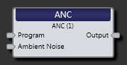
| Program node | Connection point for wiring music program or page input to the ANC block |
| Ambient Noise node |
The ANC’s ambient noise detector is fed from a side-chain input node, allowing separate processing. Connect your ambient noise input signal to this, which is from a microphone(s) in the room where the Program source is playing. tip: A RAD17 boundary microphone works well as an ambient noise input source. |
| Output node | Connection point for wiring the gain-adjusted input signal to another block, typically an output block. |
(Hover over the thumbnail below to view the properties dialog box.)

| UI Element | Purpose |
|---|---|
| Inputs |
The meter in the top portion of this area shows the signal level of the Program input node. In the bottom portion of the this area, the Detected Noise meter shows the ambient noise level that the block is sensing and using to adjust the gain of the program signal. This meter displays a filtered value of the signal received on the Ambient Noise input. The horizontal white bar on the meter corresponds to the threshold setting. |
|
Response graph/meter |
Graphical representation of signal processing. Use the green handles to adjust Threshold and Gain. The Gain parameter sets a maximum gain if above unity and a minimum gain if below unity. A real-time meter shows the ANC Gain calculated by the gain computer. |
| Output | A signal meter displays the peak and rms levels of the ANC's output channel. |
| Gain Calculation |
If the Gain setting is above unity, Threshold sets the level (in dBFS) above which the detected ambient noise signal begins to amplify the signal. If the Gain setting is less than unity, Threshold sets the level below which the detected ambient noise signal begins to attenuate the signal. Gain sets the maximum gain or attenuation allowed. When the Gain setting is positive, this control sets the maximum gain. When the Gain setting is negative, this control sets the maximum attenuation. Ratio sets the slope (ratio) of Detected Noise level change (x-axis) to output level change (Y-axis on the graph) normalized to a 1 dB output change. The Ratio determines how aggressively the ANC block amplifies (or attenuates) the program signal when the detected noise is above (or below) the Threshold. |
| Rate Control |
Response Time specifies the time in seconds it takes to adjust to a change in the ambient input noise signal. A longer response time means that the ANC will be less responsive to temporary changes as temporary changes will be averaged out over the longer time period. A shorter time means that it will be more responsive to temporary changes. For example, if the ANC gain is currently at 0 dB and a 10 second response time is selected, if you instantly change the noise level enough to drive the ANC block to reach its maximum gain/attenuation it will take 10 seconds for the ANC block to reach the final gain value (10 seconds is the selected response time). |
| Advanced |
Force Gain causes the block to apply maximum gain (if Gain is positive) and maximum attenuation (if Gain is negative). Restart causes the block to reset the noise compensation algorithm and re-characterize the detected noise. This control allows the ANC gain to quickly return to unity and clears the detected noise rms level. This can be helpful during setup. |
| Bypass | When checked, Bypass connects the input directly to the output, creating a wire. The output meter continues to operate and a yellow bar appears at the bottom of the block in the Processing Map, indicating bypass. |

 See Also