Toggles
This section explains how to integrate HAL toggle controls with buttons on an XPanel by examining a couple of touch panel applications: a preset toggle button and a wall toggle button. We start by breaking down the logic symbols and signal flow for the HAL toggle controls. Then we examine how to bind the HAL toggle controls to toggle buttons in the touch panel user interface.
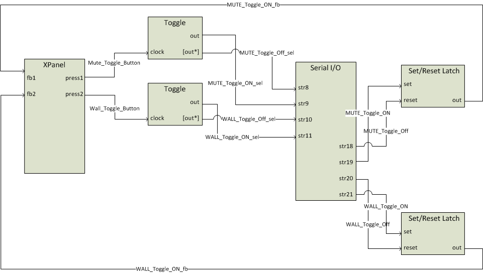
Toggles in a HAL system have only an on or off state. They are represented as checkboxes in the Halogen software and DR remotes. Because toggles only have two states, they are modeled as digital signals in SIMPL. The example program has symbols to deal with toggle button presses on a touch panel and toggle messages from a Halogen/HAL. Trace through the Toggle Control Signal Flow diagram to get an overview of how these symbols work together before we look at them up close.
Open the Rane_HAL.smw program file in SIMPL Windows. There are two HAL toggle controls in this program uniquely identified by HAL control numbers 4 and 5. These HAL control numbers appear in the Toggle tab of Halogen’s External Control Systems dialog as Mute Toggle Control and Wall Toggle Control.
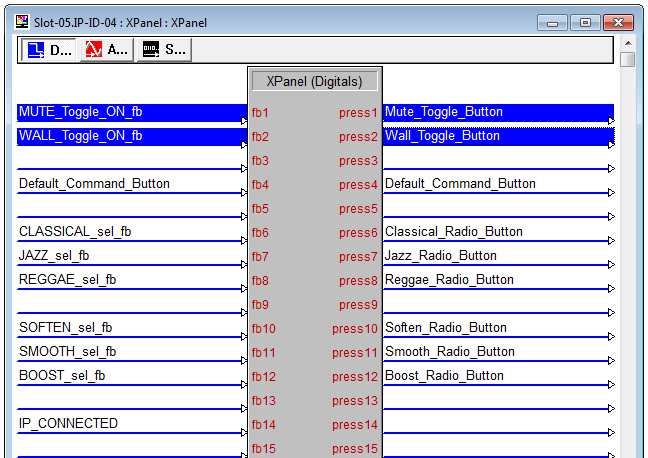
Double-click the XPanel symbol under Slot-05 of the MC2E in the Program View. The Mute Toggle Control maps to the digital fb1 input and press1 output on the XPanel. The Wall Toggle Control maps to the digital fb2 input and press2 output on the XPanel. The outgoing press signals for the two toggle buttons on the XPanel are named Mute_Toggle_Button and Wall_Toggle_Button. A press signal from an XPanel goes high when that touch panel button is pressed and falls back down to low as soon as it is released.
Double-click the Serial I/O and Serial Send symbols under Logic in the Program View to bring up their details. The controller modifies HAL toggle control values by sending message strings to Halogen/HAL. These ‘set toggle’ messages are strings comprised of a toggle control type, HAL control number and value. The valid ‘set toggle’ messages for the two HAL toggle controls in this program are <T&4&0>, <T&4&1>, <T&5&0> and <T&5&1>.
The controller also requests HAL toggle control values by sending message strings to the Halogen/HAL. These ‘get toggle’ messages are comprised of a toggle control type and HAL control number. The valid ‘get toggle’ messages for the two HAL toggle controls in this program are <T&4> and <T&5>. Halogen/HAL responds to these ‘get toggle’ messages with corresponding ‘set toggle’ messages.
note: Refer to Appendix A External Control Message Protocol for more information on toggle messages.
The ‘get toggle’ messages for the two HAL toggle controls appear in the string parameter of the Serial Send symbol that is triggered whenever the TCP/IP Client connects to Halogen/HAL. Requesting the toggle values on connect ensures that the toggle buttons on the XPanel are in sync with the live toggle values on Halogen/HAL.
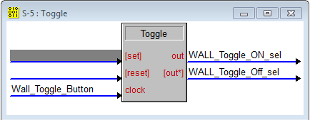
Double-click one of the two Toggle symbols under Logic in the Program View to bring up its details. Each toggle button press signal from the XPanel drives a clock input on a Toggle symbol. The Toggle symbol translates the button press into separate toggle ON_sel and toggle Off_sel signals. When the toggle ON_sel signal is high the toggle Off_sel signal is low and vice versa. These signals are latched by the Toggle symbol so that when you let go of a toggle button on a touch panel it stays in its new on or off state.
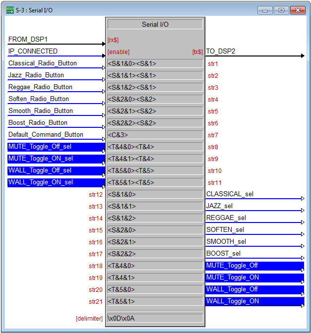
The two Toggle symbols -- outgoing toggle ON_sel and toggle Off_sel signals -- are what trigger the ‘toggle set’ messages sent by the Serial I/O. Take the Mute_Toggle_Off_sel signal, for instance. When that signal goes high, a ‘set toggle’ message to turn HAL toggle control 4 off is sent. The ‘set toggle’ message is immediately followed by a ‘get toggle’ message for the same HAL toggle control. Remember to include a ‘get toggle’ message with any 'set toggle' message because Halogen/HAL does not echo a ‘set toggle’ message back to the client that sent it. This is needed because the visible state of a touch panel toggle button is determined by its feedback signal and feedback is only generated from incoming 'set toggle' messages.
Signals coming out of the Serial I/O go high when matching message strings are received from Halogen/HAL. Take the Mute_Toggle_Off signal, for example. This signal goes high when a ‘set toggle’ message string of <T&4&0> is received. The signal won’t go low again until another character is received and a match with the rightmost characters of the input string no longer exists. The same technique applies to the Mute_Toggle_On signal when a ‘set toggle’ message string of <T&4&1> is received.
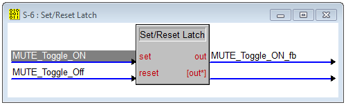
Double-click one of the two Set/Reset Latch symbols under Logic in the Program View to bring up its details. Notice that Toggle_ON and Toggle_Off signals from the Serial I/O drive the set and reset inputs. The Set/Reset Latch merges the two inputs into a single Toggle_ON_fb signal. This outgoing feedback signal is latched so that when a toggle value change is received the toggle button stays in its new on or off state.
The feedback signals from the Set/Reset latches drive the fb1 and fb2 feedback inputs for the two toggle buttons on the XPanel. These feedback signals are generated by the ‘set toggle’ message the Serial I/O receives from Halogen/HAL. These ‘set toggle’ messages are the same strings sent by the Serial I/O when toggle buttons are pressed on the XPanel. They may arrive unsolicited or in response to a 'get toggle' message.
note: Refer to Appendix A External Control Message Protocol for more information on toggle messages.
Toggle Presets
This example demonstrates how to get a toggle button on a touch panel to activate and deactivate a Halogen/HAL preset. The example Halogen configuration file contains a toggle preset for muting and unmuting all the outputs on a HAL. This Mute All Preset is linked to a Control Systems toggle control named Mute All Toggle Control. Toggling this HAL control activates or deactivates the preset.
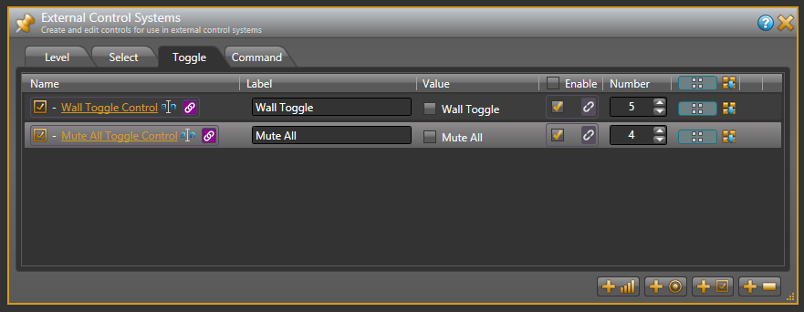
Open the ControlSystemSample.hal example configuration file in Halogen. Then open the External Control Systems dialog and select the Toggle tab. The Value checkbox for the Mute All Toggle Control reflects the current state of that HAL toggle control.
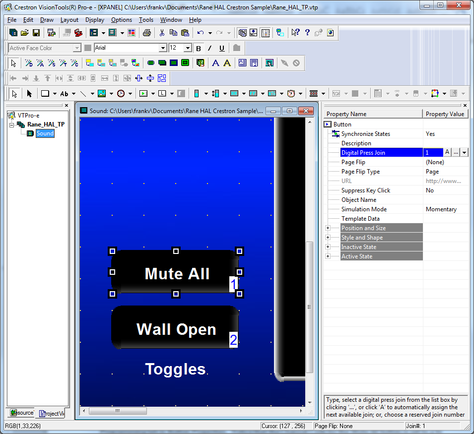
Open the Rane_HAL_TP.vtp project file in Vision Tools Pro-e. Next, open the Sound page window to view the example touch panel design. Select the Mute All button in the Sound page window. Notice that the Digital Press Join number for the Mute All button is set to 1 to match the fb1 input and press1 output on the XPanel symbol in the program. The button will appear raised when it is in its inactive state and depressed when it is in its active state.
Launch the XPanel and verify that the Connected status indicator shows you are connected. Refer to the Troubleshooting section if it the status indicator says Disconnected. Click the Mute All button on the XPanel on and off. The touch panel button will remain in its new active or inactive state after you release the mouse button. This is the latching behavior alluded to earlier. Now watch the Active state of the Mute All Preset in Halogen as you click the Mute All button on the XPanel. Lastly toggle the Mute All Preset from Halogen to see that the Mute All button and Lounge slider on the XPanel respond.
note: Refer to Appendix B Using PuTTY to Test External Control Systems for help with debugging if the system does not behave as described here.
Wall Toggles
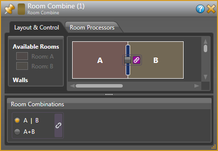
This example demonstrates how to get a toggle button on a touch panel to open and close a movable wall in a Halogen/HAL Room Combine block. The example Halogen configuration file contains a Room Combine block with two rooms A and B. The movable wall in between these two rooms is linked to a Control Systems toggle control named Wall Toggle Control. Toggling this HAL control opens and closes the wall.
Open the ControlSystemSample.hal example configuration file in Halogen, then open the External Control Systems dialog and select the Toggle tab. The Value checkbox for the Wall Toggle Control reflects the current state of that HAL toggle control.
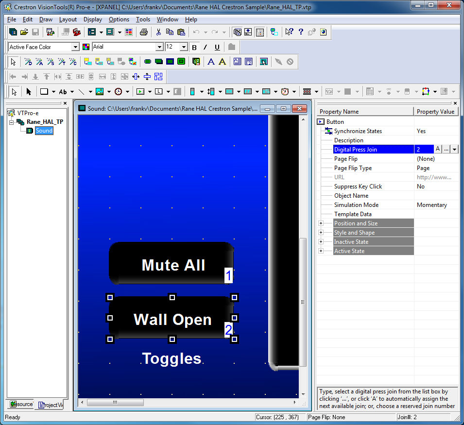
Open the Rane_HAL_TP.vtp project file in Vision Tools Pro-e. Next, open the Sound page window to view the example touch panel design. Select the Wall Open button in the Sound page window. Notice that the Digital Press Join number for this button is set to 2 to match the fb2 input and press2 output on the XPanel symbol in the program. The touch panel button will appear raised when it is in its inactive state and depressed when it is in its active state.
Double-click the Room Combine (1) block in the Halogen Processing map to open its properties dialog. Select the Layout and Control tab in the Room Combine (1) dialog. Launch the XPanel and verify that the Connected status indicator shows that you are connected. Refer to the Troubleshooting section if it the status indicator says Disconnected. Watch the wall between rooms A and B appear and disappear as you click the Wall Open button on the XPanel open and closed. Now toggle the wall open and closed from the Room Combine (1) dialog and watch that same button turn on and off on the XPanel.
note: Refer to Appendix B Using PuTTY to Test External Control Systems for help with debugging if the system does not behave as described here.