Selectors
This section explains how to integrate HAL selector controls with buttons on an XPanel by examining a couple of touch panel applications: input source selector radio buttons and preset selector radio buttons. We start by breaking down the logic symbols and signal flow for the HAL selector controls. Then we examine how to bind the HAL selector controls to radio buttons in the touch panel user interface.
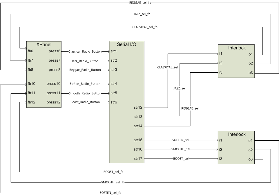
At its simplest, a HAL selector control is just a selection integer value. The range of this selection value is constrained by the number of positions on the selector. For instance, a HAL three-way selector can only have a value of 0, 1 or 2. The example program contains symbols to deal with radio buttons on a touch panel and selector messages received from Halogen/HAL. Trace through the Selector Control Signal Flow diagram to get an overview of how these symbols work together before we look at them up close.
Open the Rane_HAL.smw program file in SIMPL Windows. There are two HAL selector controls in this program uniquely identified by HAL control numbers 1 and 2. These HAL control numbers appear in the Selector tab of Halogen’s External Control Systems dialog as Source Selector Control and PEQ Selector Control. (PEQ stands for parametric equalizer.)
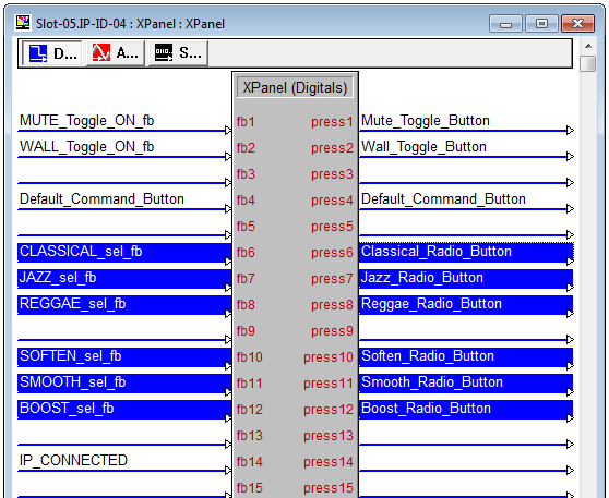
Double-click the XPanel symbol under Slot-05 of the MC2E under Logic in the Program View to bring up its details. The radio buttons for the two selectors are divided into two groups on the XPanel. The Classical, Jazz and Reggae radio buttons assigned to digital signals 6, 7 and 8 make up the Source selector group. The Soften, Smooth and Boost radio buttons assigned to digital signals 10, 11 and 12 make up the Tone selector group.
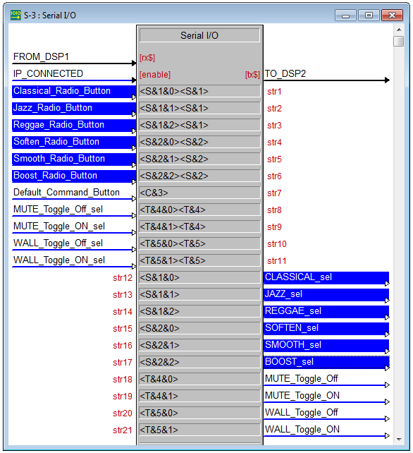
Double-click the Serial I/O and Serial Send symbols under Logic in the Program View to bring up their details. Clicking a selector radio button on the XPanel sends a message string to Halogen/HAL. These ‘set selector’ messages are comprised of a selector control type, HAL control number and value. The valid ‘set selector’ messages for the source selector in this program are <S&1&0>, <S&1&1> and <S&1&2>. The valid ‘set selector’ messages for the PEQ selector in this program are <S&2&0>, <S&2&1> and <S&2&2>.
The controller also requests HAL selector control values by sending message strings to Halogen/HAL. These ‘get selector’ messages are comprised of a selector control type and HAL control number. The valid ‘get selector’ messages for the two HAL selector controls in this program are <S&1> and <S&2>. Halogen/HAL responds to these ‘get selector’ messages with corresponding ‘set selector’ messages.
note: Refer to Appendix A External Control Message Protocol for more information on selector messages.
The <S&1> and <S&2> ‘get selector’ messages appears in the string parameter of the Serial Send symbol that is triggered whenever the TCP/IP Client connects to Halogen/HAL. Requesting the selector values on connect ensures that the radio buttons on the XPanel are in sync with the live selector values on Halogen/HAL.
Append ‘get selector’ messages to the ‘set selector’ messages that the Serial I/O sends out because Halogen/HAL does not echo a ‘set selector’ message back to the client that sent it. For instance, clicking on the Reggae radio button on the XPanel sends <S&1&2> followed by <S&1> to Halogen/HAL. Upon receipt of the resulting <S&1&2> from Halogen/HAL the Serial I/O’s outgoing REGGAE_sel signal goes high. The program relies on the response triggered by the ‘get selector’ message to drive the feedback for a selector’s radio buttons.
Double-click one of the two Interlock symbols under Logic in the Program View to bring up its details. An Interlock latches an output signal high on the rising edge of its input while forcing all the other outputs low. The last input to go high determines which output gets latched high. An Interlock is the simplest way to achieve mutual exclusion needed for a group of selector radio buttons.
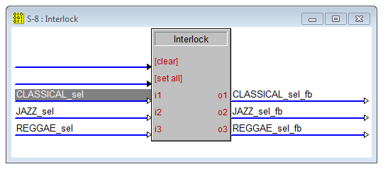
Take the source selector’s Interlock, for example. It handles the CLASSICAL_sel, JAZZ_sel and REGGAE_sel signals from the Serial I/O. When the REGGAE_sel signal goes high the REGGAE_sel_fb signal gets latched high and the CLASSICAL_sel_fb and JAZZ_sel_fb signals are latched low. The end result is that the Reggae radio button on the XPanel is activated and the Classical and Jazz radio buttons are deactivated.
Source Selector
This example demonstrates how to get radio buttons on a touch panel to switch between input source selections on a HAL. The example Halogen configuration file contains a selector block wired to three HAL mic/line Inputs. The input nodes on the selector block are named Classical, Jazz and Reggae for the genre of music being fed into each of them. This selector block is linked to a HAL Control Systems selector control named Source Selector Control. Switching selections on the Source Selector Control switches the selected input on the selector block.
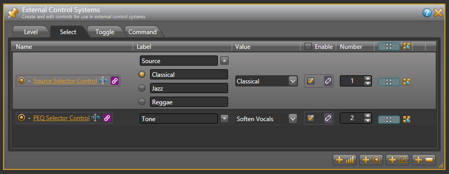
Open the ControlSystemSample.hal example configuration file in Halogen. Then open the External Control Systems dialog and select the Selector tab. The selected item in the Value column for the Source Selector Control is the input currently selected by that selector in the system. The set of radio buttons also reflects the current selection. Select a different item for the Source Selector Control to choose a different input.
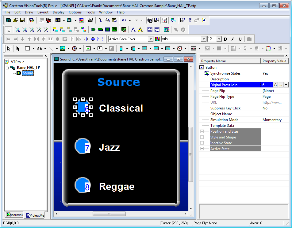
Open the Rane_HAL_TP.vtp project file in Vision Tools Pro-e. Next, open the Sound page window to view the example touch panel design. Select the circular Classical radio button in the Sound page window. Notice that the Digital Press Join number for that button is set to 6 to match the fb6 input and press6 output on the XPanel symbol in the program. The Digital Press Join numbers for the other two source selector radio buttons are 7 and 8. A radio button will appear blue when it is in its active state and blacked out when it is in its inactive state.
Launch the XPanel and verify that the Connected status indicator shows you are connected. Refer to the Troubleshooting section if it the status indicator says Disconnected. Double-click the Selector (1) block in the Halogen Processing map to bring up its properties dialog. Click on the Jazz radio button in the Selector (1) Block dialog. Then click on the Classical radio button on the XPanel. The selected input in Halogen switches from Jazz to Classical. Now click on the Reggae radio button in Halogen. The Classical radio button is selected and the Reggae radio button is deselected on the XPanel.
note: Refer to Appendix B Using PuTTY to Test External Control Systems for help with debugging if the system does not behave as described here.
Preset Selector
This example demonstrates how to get radio buttons on a touch panel to switch between presets on a HAL. The example Halogen configuration file contains a Parametric EQ block. Different EQ filter settings for this block are saved to different presets. One preset softens vocals, another smooths out the mid-range and a third boosts the bass. These three presets belong to the same PEQ Preset Selector. This selector is linked to a HAL Control Systems selector control named PEQ Selector Control. Switching selections on the PEQ Selector Control switches the active preset in the PEQ Preset Selector.
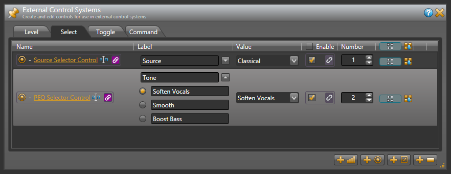
Open the ControlSystemSample.hal example configuration file in Halogen. Then open the External Control Systems dialog and select the Selector tab. The selected item in the Value column for the PEQ Selector Control is the preset currently selected by that selector in the system. The set of radio buttons also reflects the current selection. Select a different item for the PEQ Selector Control to choose a different PEQ preset.
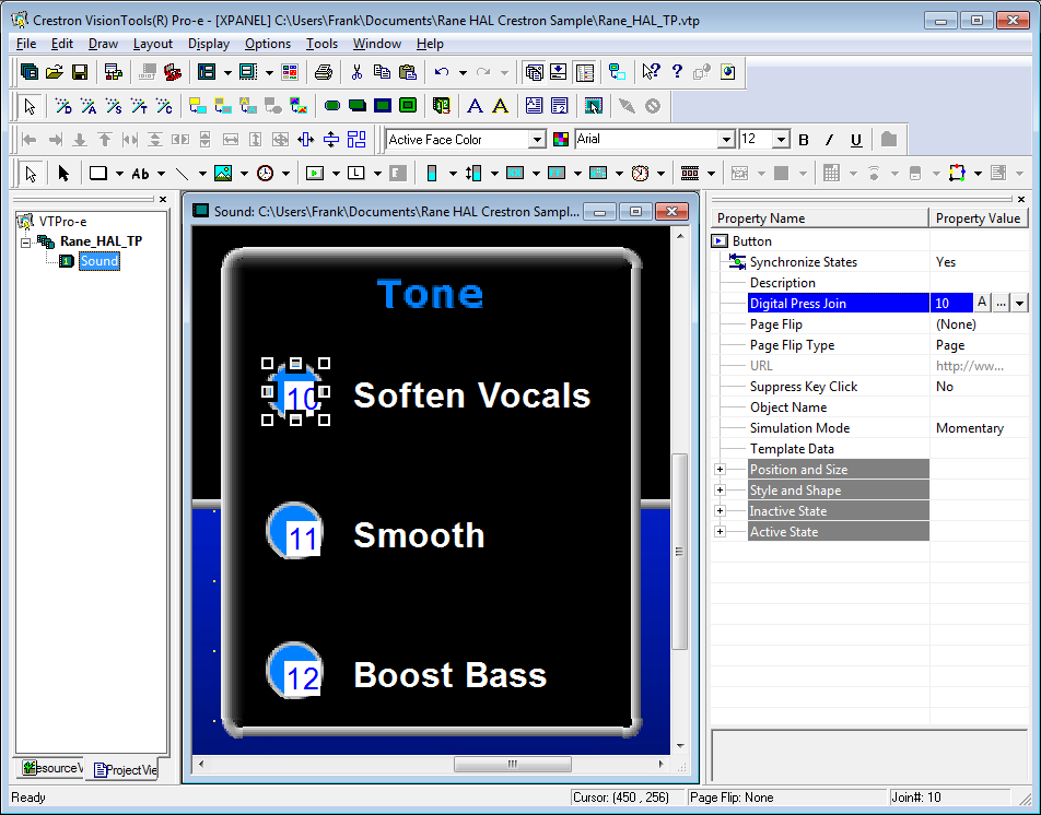
Open the Rane_HAL_TP.vtp project file in Vision Tools Pro-e. Next, open the Sound page window to view the example touch panel design. Select the circular Soften Vocals radio button in the Sound page window. Notice that the Digital Press Join number for that radio button is set to 10 to match the fb10 input and press10 output on the XPanel symbol in the program. The Digital Press Join numbers for the other two tone selector radio buttons are 11 and 12. A radio button will appear blue when it is in its active state and blacked out when it is in its inactive state.
Launch the XPanel and verify that the Connected status indicator shows that you are connected. Refer to the Troubleshooting section if it the status indicator says Disconnected. In Halogen, click on the Presets icon in the Processing Workspace toolbar to bring up the All Presets dialog. Choose the Selector tab in that dialog and expand the PEQ Preset Selector so that its contents are visible. Click the Smooth radio button in the All Presets dialog. Then click on the Soften Vocals radio button on the XPanel. The selected preset in Halogen switches from Smooth to Soften Vocals. Now click on the Boost Bass radio button in Halogen. The Boost Bass radio button is selected and the Soften Vocals radio button is deselected on the XPanel.
note: Refer to Appendix B Using PuTTY to Test External Control Systems for help with debugging if the system does not behave as described here.