Levels
This section explains how to integrate HAL level controls with sliders on an XPanel by looking at a volume slider on a touch panel. We start by breaking down the logic symbols and signal flow for the HAL level control. Then we examine how to bind the HAL level control to a slider in the touch panel user interface.
The level controls on a HAL that are accessible to an external controller have a value range of 0 to 1000. Compare that with the 0 to 65535 range of Crestron analog signals. This discrepancy requires a Crestron controller to convert the level values it gets from and sends to a HAL. HAL levels map naturally to sliders on Crestron touch panels. The example program contains symbols to deal with slider movements on a touch panel and level messages from a HAL. Let’s take a look at them.
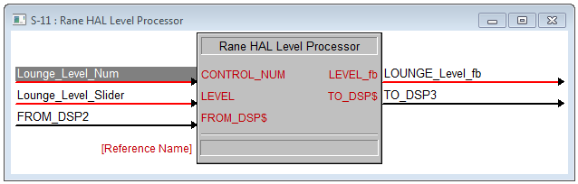
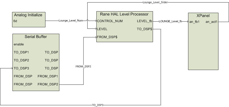
Open the Rane_HAL.smw program file in SIMPL Windows. Double-click the Rane HAL Level Processor symbol under Logic in the Program View to bring up its details. There is one HAL level control in this program uniquely identified by HAL control number 6. This control number appears in the Level tab of Halogen’s External Control Systems dialog as Lounge Level Control. It is also fed to the CONTROL_NUM input of the Rane HAL Level Processor by an Analog Initialize symbol.
The Rane HAL Level Processor has two more inputs and two more outputs. The FROM_DSP input is driven by the $RX output on the HAL’s TCP/IP Client. The TO_DSP output drives the $TX input on the HAL’s TCP/IP Client. The LEVEL input is driven by the analog output from a slider on the XPanel. The LEVEL_fb signal drives the analog feedback input for that same slider. Dragging the slider on the touch panel causes the Rane HAL Level Processor to convert changes in the LEVEL analog input to appropriate HAL Level values and send ‘set level’ messages to Halogen/HAL. These ‘set level’ messages contain a level control type, HAL control number and level value. Valid ‘set level’ messages for the HAL level control in this example program are <L&6&0>, <L&6&1>, <L&6&2> all the way to <L&6&1000>.
Halogen/HAL sends these same ‘set level’ messages to the controller whenever another client changes a HAL level control value. These ‘set level’ messages from Halogen/HAL are processed by the Rane HAL Level processor which converts them from the HAL level range to Crestron analog signal range, resulting in feedback to the touch panel slider.
The controller also requests HAL level control values by sending message strings to Halogen/HAL. These ‘get level’ messages are comprised of a level control type and HAL control number. The ‘get level’ message for the HAL level control in this program is <L&6>. Halogen/HAL responds to this ‘get level’ message with a corresponding ‘set level’ message.
note: Refer to Appendix A External Control Message Protocol for more information on level messages.
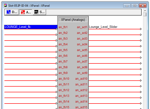
Double-click the XPanel symbol under Slot-05 of the MC2E in the Program View to bring up its details. Click on the Analogs button on the top bar of the XPanel details window. The Rane HAL Level Processor for the Lounge Level Control maps to the an_fb1 input and an_act1 output on the XPanel. The incoming feedback signal is named Lounge_Level_fb. The outgoing touch panel slider signal is named Lounge_Level_Slider.
The <L&6> ‘get level’ message appears in the string parameter of the Serial Send symbol that is triggered whenever the TCP/IP Client connects to Halogen/HAL. Requesting the level value on connect ensures that the slider on the XPanel is in sync with the live level value on Halogen/HAL.
The Rane HAL Level Processor is a user module written in SIMPL+. Right-click on it under Logic in the Program View and select Edit User Module to view its source code. The user module parses and encodes ‘set level’ messages and converts from Crestron analog to HAL level values and back. A full listing of the user module source code is available in Appendix C .
Because the Rane HAL Level Processor is a user module, you can add multiple instances of this symbol to your own programs for more HAL levels. First, drag it from the Symbol Library and drop it into your Program View as you would any of the stock logic symbols. Then initialize the CONTROL_NUM input and route the rest of the ins and outs to the XPanel, e-control TouchPanel and TCP/IP Client.
Sliders
This example demonstrates how to get a slider on a touch panel to manipulate the level on a HAL output. The example Halogen configuration contains a HAL line output wired to a lounge. The remaining HAL line outputs go to rooms A and B. The level on the lounge output is linked to a HAL Control Systems level control named Lounge Level Control. Adjusting the HAL level control alters the level.
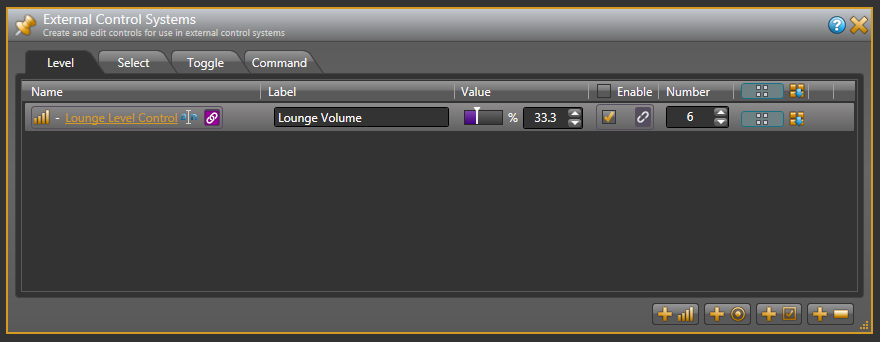
Open the ControlSystemSample.hal example configuration file in Halogen. Then open the External Control Systems dialog and select the Level tab. The percentage shown in the Value column for the Lounge Level Control is the live value of that level in the system. Drag the level slider in that dialog and the number shown in the edit field changes accordingly.
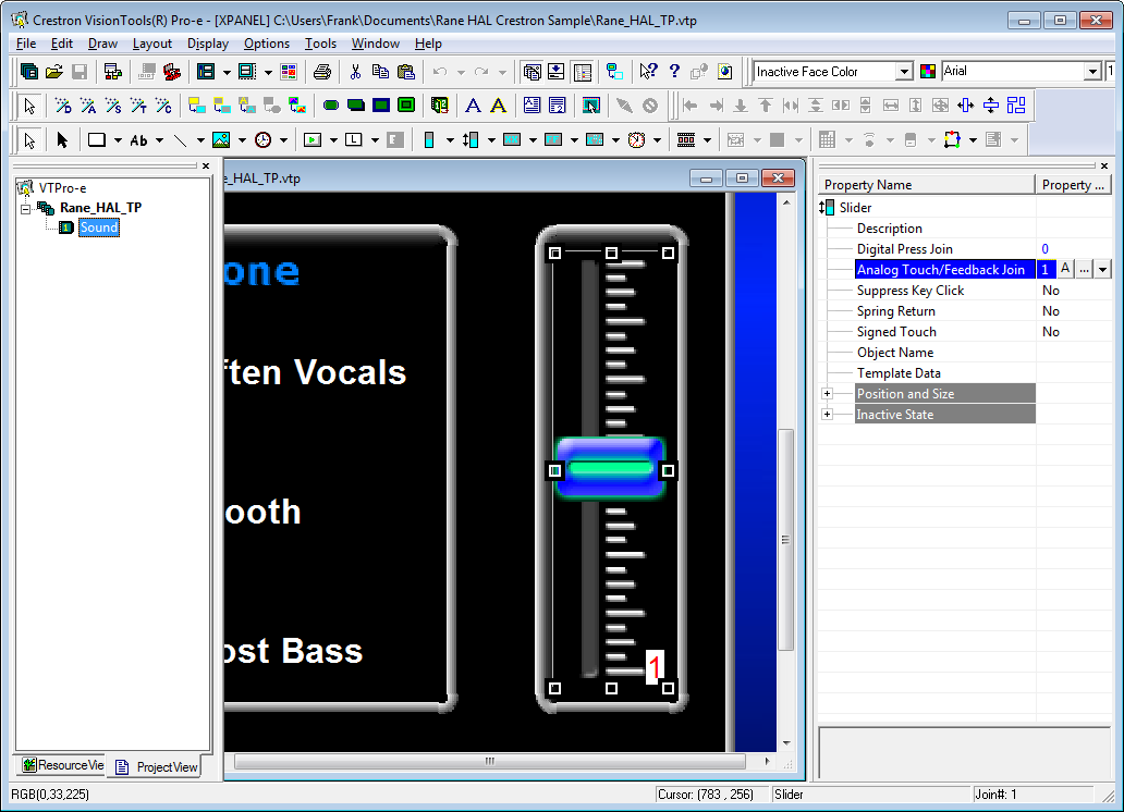
Open the Rane_HAL_TP.vtp project file in Vision Tools Pro-e. Then open the Sound page window to view the example touch panel design. Select the Lounge slider on the right side of the Sound page window. Notice that the Analog Touch/Feedback Join number for this slider is set to 1 to match the an_fb1 input and an_act1 output on the XPanel symbol in the program. The slider’s output is routed to the LEVEL input of the Rane HAL Level Processor. The slider’s input is driven by the LEVEL_fb output of the Rane HAL Level Processor.
Launch the XPanel and verify that the Connected status indicator shows that you are connected. Refer to the Troubleshooting section if it the status indicator says Disconnected. Drag the Lounge slider up and down on the XPanel to adjust the level continuously. The percentage shown for the Lounge Level Control in Halogen fluctuates with your slider movements. Double-click the HAL Line Output (1) block in the Halogen Processing map to bring up its properties dialog. Now drag the slider for the level in HAL Line Output (1) block dialog back and forth in Halogen. The slider on the XPanel moves up and down in conjunction with the level.
note: Refer to Appendix B Using PuTTY to Test External Control Systems for help with debugging if the system does not behave as described here.