Getting Started
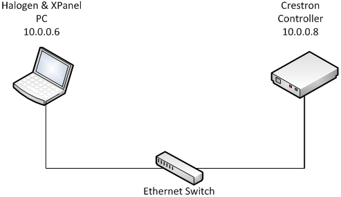
This section shows how to set up your system so that you can get the most out of the examples. The principal components of your system are the Windows PC and Crestron controller. Both should reside on the same network so that they can communicate easily. Configure their IP settings and plug them into the Ethernet switch using the Ethernet cables.
Launch Halogen on the PC so that it can pretend to be a HAL. A virtual HAL starts running on your PC when you launch Halogen. This process goes away when you exit Halogen. Make sure to have the right configuration file open in Halogen when testing your system. Use the ControlSystemSample.hal file that came with the Crestron Support Package when working with the examples.
Minimal Example Network
In addition to substituting for a HAL, the PC will also act as a touch panel by using the standalone XPanel desktop application generated by Vision Tools Pro-e. The XPanel executable should be targeted for Windows PCs.
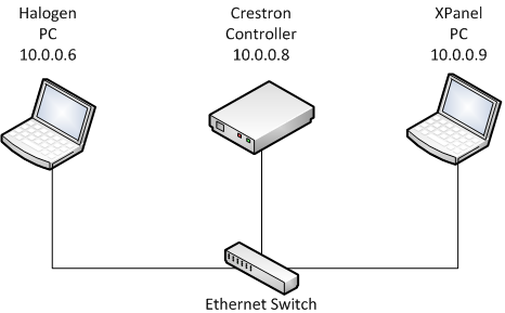
Later on you can choose to run the XPanel on a different PC to simulate a more realistic installation environment. For now, run Halogen and the XPanel on the same PC as shown in the Minimal Example Network diagram.
Run the example program on the controller so that it can talk to Halogen Control Server and the XPanel. Open the Rane_HAL.smw program file in SIMPL Windows. Switch to the Configuration Manager. If your controller is not an MC2E, right-click on the MC2E node in the lower System Views pane and select Replace “MC2E” from the context menu to bring up the Select New Device dialog. Select the model of your controller from that dialog and click the OK button. Change the server address of the TCP/IP client and the IP address of the XPanel so that they both match your PC’s IP address. Compile the program and transfer the resulting Rane_HAL.spz file to your controller.
Compile and run the XPanel on the PC so that it can talk to the controller. User interface widgets on the XPanel are assigned to specific outputs in the program so the two depend on each other. Open the Rane_HAL_TP.vtp project file in Vision Tools Pro-e and hit F12 to compile it. This will generate a Rane_HAL_TP.exe folder in the same directory as the project. Double-click the LaunchXPanel.exe file located in this new directory to run the XPanel.
You know all of the components of your system are communicating properly when the Connected status indicator in the upper right corner of the XPanel is blue. If the XPanel fails to connect to the controller on startup, an error pop-up dialog saying “Control System Connection: Disconnected” will eventually appear. If this dialog does not come up but the connected status indicator is still blacked out then the controller is not connecting to Halogen. Refer to Troubleshooting if you find yourself struggling to establish communications.